Generator armature

a technology of generators and armatures, which is applied in the direction of electric generator control, machine/engine, magnetic circuit shape/form/construction, etc., can solve the problems of undesirable high temperature in the windings, high electrical current in the windings, so as to reduce the effective cooling of the windings over their entire length, increase the efficiency of heat transfer from the windings, and reduce the effect of cooling airflow in the axial cooling channel

Active Publication Date: 2015-12-24
FLENDER GMBH
View PDF7 Cites 10 Cited by
  • Summary
  • Abstract
  • Description
  • Claims
  • Application Information

AI Technical Summary

Benefits of technology

[0027]A cooling airflow can enter the armature at one end, for example at the drive end, and then pass along the axial cooling channels, whereby the cooling airflow will also pass into the series of inward-facing openings of the radial cooling channels. The effectiveness of the cooling airflow in an axial cooling channel may therefore be reduced by the time the remainder reaches the other end of that axial cooling channel. As a result, particularly when the generator is operating at or above its rated power, the stator windings may be optimally cooled at the airflow entry end (for example at the drive end) but less than optimally cooled at the opposite airflow exit end. Therefore, in a preferred embodiment of the invention, the cooling arrangement is realized to convey the cooling airflow into the axial cooling channel at both ends, i.e. from openings at the drive end of the armature and at the non-drive end of the armature. The cooling airflow can be forced into or drawn into the axial cooling channels and then forced or drawn into the radial cooling channels and into the armature interior cavity. In this way, a very effective cooling of the windings over the

Problems solved by technology

During operation of a generator such as a wind turbine generator, high levels of electrical current are induced in the windings, and these become very hot as a result.
A high temperature in the windings is undesirable for a number of reasons.
The resistance of the windings increases at higher temperatures, with a detrimental effect on the generator's output power.
Also, the heat from the generator is passed to the magnets and can have an adverse effect on their performance.
Therefore, much effort is invested in attempting to cool the generator.
However, these approaches are all limited to some extent by the generator design, specifically by constraints that affect the stator design.
For example, in most designs it is not possible to access the hot windings directly since each winding is closely packed between adjacent stator teeth.
In other designs it is not possible to access the windings or the stator supporting structure for cooling purposes.
Therefore, the effectiveness of the known designs is limite

Method used


Image

  • Generator armature
  • Generator armature
  • Generator armature

Examples


first embodiment

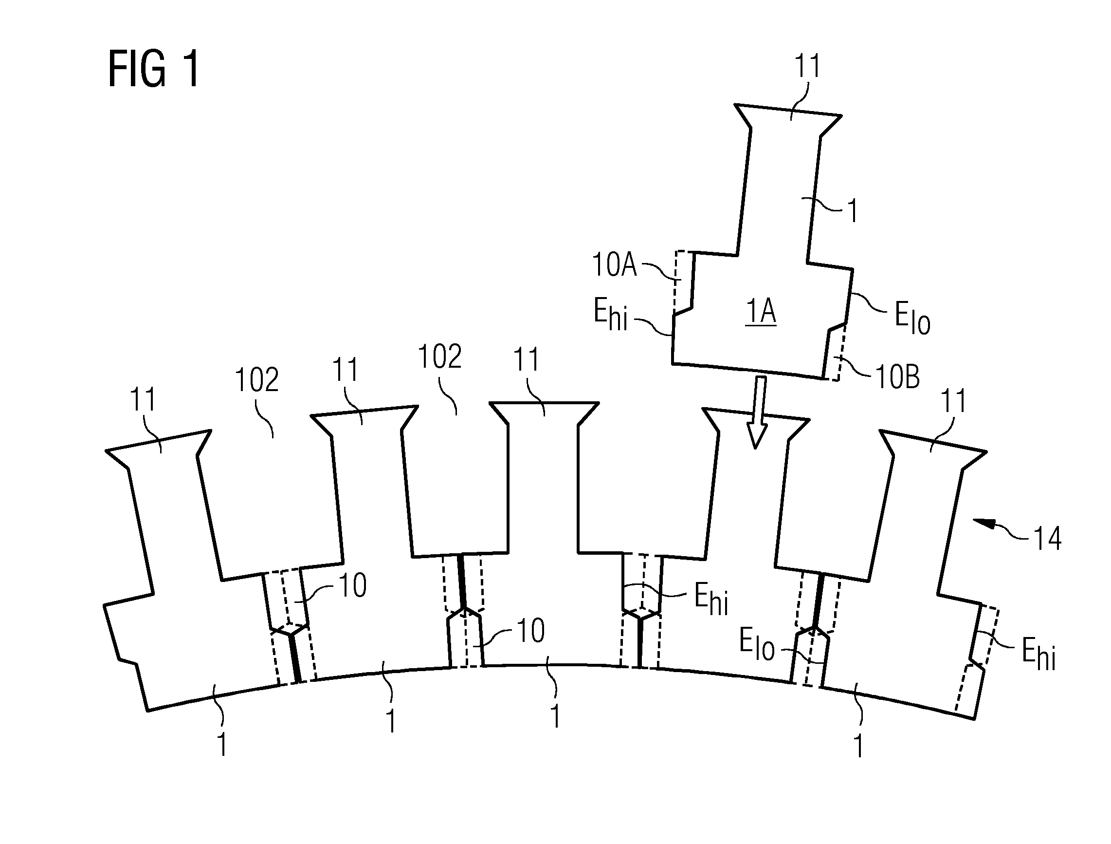
[0038]FIG. 1 shows a schematic representation of a laminate sheet 1 according to embodiments of the invention. The diagram indicates the positions of a number of identical laminate sheets 1 with a first shape 1A in an annular laminate layer 14 (shown only partially). In this embodiment, each laminate sheet 1 comprises a single armature tooth protrusion 11. The diagram shows that the laminate sheet 1 can be “flipped” to give its mirror image, so that a series of such laminate sheets 1 can be assembled to give the annular laminate layer 14. For an armature with n poles, n such laminate sheets 1 are required in each annular laminate layer 14 or laminate sheet ring 14. The number of annular layers 14 required to assemble a stack will depend on the depth of the armature. When stacked, the armature tooth protrusions 11 result in an arrangement of armature teeth separated by axial winding slots 102 into which the stator windings can be placed.

[0039]The diagram shows that each laminate shee...

second embodiment

[0044]FIG. 5 shows a schematic representation of a laminate sheet 1 according to embodiments of the invention. Here also, the diagram indicates the position of the laminate sheet 1 in an annular laminate layer 14. In this embodiment, each laminate sheet 1 comprises an odd number of stator tooth protrusions 11, two complementary side edges Ehi, Elo to give notch portions 10A, 10B, and an even number of complete notches 10. In this case also, the laminate sheet 1 can be “flipped” to give its mirror image, and a series of such laminate sheets 1 can be assembled to give an annular laminate layer. By offsetting a stack of such layers from another layer stack by one stator tooth, so that a series of “upper” notches adjoins a series of “lower” notches, a labyrinthine arrangement of radial cooling channels is achieved as explained in FIG. 1 above.

[0045]Although the present invention has been disclosed in the form of preferred embodiments and variations thereon, it will be understood that nu...


PUM


Abstract

A generator armature including a plurality of laminate sheets stacked to form an annular arrangement of armature teeth, whereby each pair of adjacent armature teeth is separated by an axial winding slot extending a direction essentially parallel to an axis of rotation of the generator; and a plurality of radial cooling channels, whereby a radial cooling channel is realized to transport a cooling medium and extends from an axial winding slot to an interior cavity of the generator, and wherein a radial cooling channel includes a series of aligned notches in the laminate sheets of a laminate stack is provided. A laminate sheet for an armature of a generator, a cooling arrangement, a generator, a wind turbine, and a method of cooling stator windings arranged on an armature of a generator is also provided.

Description

CROSS-REFERENCE TO RELATED APPLICATIONS[0001]This application claims priority to EP Application No. 14172957.4, having a filing date of Jun. 18, 2014, the entire contents of which are hereby incorporated by reference.FIELD OF TECHNOLOGY[0002]The following describes a generator armature, a laminate sheet, a cooling arrangement realized to cool stator windings of a generator, a generator, a wind turbine, and a method of cooling the stator windings of a generator.BACKGROUND[0003]In the known generator designs in which an inner or outer stator acts as the armature, the stator is loaded with a plurality of windings or coils, and a corresponding rotor is loaded with magnets or magnet pole pieces. The armature itself is usually made by stacking laminate sheets of a suitable material such as electrical steel or silicon steel, and arranging these about a supporting structure. A laminate sheet is pre-cut or punched in the desired shape according to the required number of stator windings and s...

Claims


Application Information

Patent Timeline
IPC IPC(8): H02K9/04F03D9/00H02K9/02
CPCH02K9/04Y02E10/725H02K1/20F03D80/80F03D9/25F03D15/20F03D80/60H02K7/1838Y02E10/72
Inventor AIROLDI, GIOVANNIANDERSEN, MADS PETER ZIPPOR LETHGROENDAHL, ERIKJACOBSEN, BO NEDERGAARDSOERENSEN, PETER HESSELLUNDTHOMAS, ARWYN
Owner FLENDER GMBH
Why Eureka
Try Eureka