Work vehicle

一种作业车辆、废气处理装置的技术,应用在作业车辆领域,能够解决降低散热器冷却效率、空气通风阻力增大、发动机室空间狭窄等问题,达到抑制冷却效率降低、降低热影响、提高视野性的效果

Active Publication Date: 2012-09-12
KOMATSU LTD
View PDF3 Cites 15 Cited by
  • Summary
  • Abstract
  • Description
  • Claims
  • Application Information

AI Technical Summary

Problems solved by technology

Therefore, as described above, if the exhaust gas treatment device is housed in the engine room of the work vehicle, the space in the engine room will be narrowed.
In this case, the ventilation resistance of the air sent to the radiator increases, and as a result, the cooling efficiency of the radiator may decrease.

Method used


Image

  • Work vehicle
  • Work vehicle
  • Work vehicle

Examples


Embodiment Construction

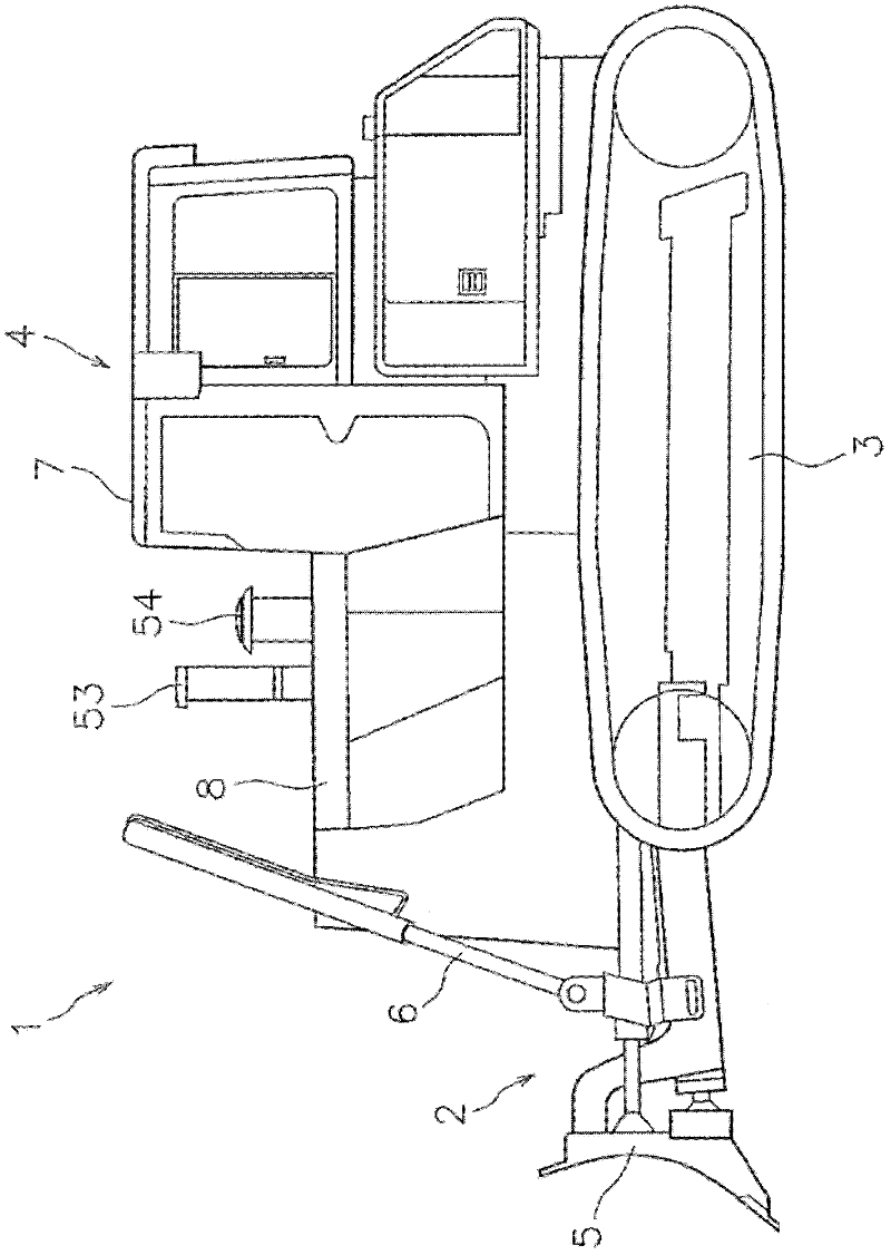
[0045] figure 1 A work vehicle 1 according to one embodiment of the present invention is shown. The work vehicle 1 is a bulldozer, figure 1 It is a left side view of the work vehicle 1 . In addition, in the following description, left-right means the left-right direction in the state which looked ahead from inside the cab 7. As shown in FIG. The work vehicle 1 includes a work implement 2 , a traveling device 3 , and a vehicle main body 4 . The working device 2 has a scraper 5 and a hydraulic cylinder 6 . The scraper 5 is arranged on the front side of the vehicle body 4 . The hydraulic cylinder 6 is driven by hydraulic pressure generated by a hydraulic pump not shown, and moves the scraper 5 up and down. The traveling device 3 is a crawler-type traveling device, and is attached to the vehicle body 4 . The vehicle body 4 has a cab 7 and an engine room 8 .

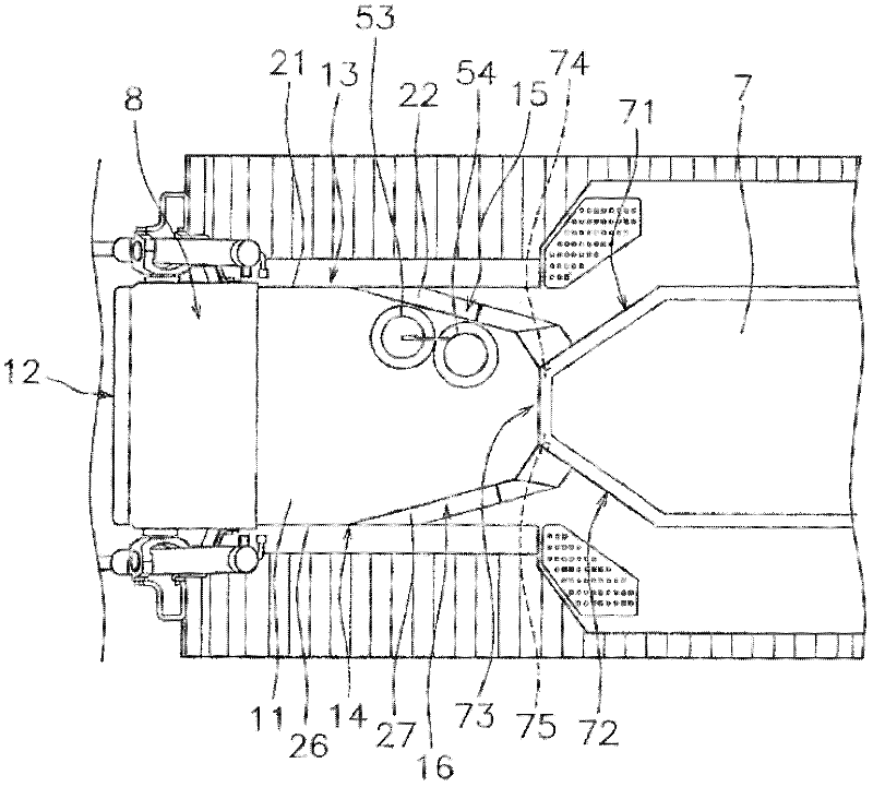
[0046] A vehicle seat and an operating device (not shown) are installed in the cab 7 . figure 2 It is a plan view ...


PUM


Abstract

In a work vehicle, an engine compartment is disposed forwards of a cab. An exhaust gas treatment device is disposed over an engine in the engine compartment. A radiator is disposed forwards of the exhaust gas treatment device (33) in the engine compartment. A blower is configured to generate an airflow passing through the radiator from back to front of the radiator. The exhaust gas treatment device is slanted with respect to a vehicle width direction for increasing a distance between the exhaust gas treatment device and the radiator towards a first lateral face portion. Further, the first lateral face portion includes air inlets facing a space between the exhaust gas treatment device and the radiator.

Description

technical field [0001] The invention relates to a work vehicle. Background technique [0002] The work vehicle includes an engine room on the front side of the cab. The engine compartment accommodates devices such as an engine, a radiator, and a blower. For example, as shown in Patent Document 1, an exhaust pipe is connected to an engine via a muffler, and the exhaust pipe protrudes from the ceiling of the engine room. The radiator is arranged on the front side of the engine. The blower generates an airflow that flows through the radiator in order to cool the coolant flowing through the radiator. In addition, a plurality of ventilation holes are provided on the side of the engine room. Here, the work vehicle performs various works with a work device such as a scraper provided at the front of the vehicle body, such as a bulldozer. In such a work vehicle, foreign matter such as dust easily enters the engine compartment from the front of the vehicle body. Therefore, in su...

Claims


Application Information

Patent Timeline
Patent Type & Authority Applications(China)
IPC IPC(8): B60K11/04B60K13/02B60K13/04E02F9/00F01N3/00F01P5/02
CPCE02F3/7609E02F9/00F01N13/1805F01N2590/08F01P5/06F01P11/10F01P2060/16B60K11/04B60K13/04B60Y2200/411
Inventor 辻智明中上博司
Owner KOMATSU LTD
Why Eureka
Try Eureka