Platform seal strip, turbine blade assembly and method for assembling it

a technology for turbine blades and seals, which is applied in the direction of valve construction, marine propulsion, forging/pressing/hammering apparatus, etc., can solve the problems of affecting engine efficiency, difficult assembly, and easy leakage, so as to improve the cooling of the blade, improve the sealing of the turbine hot blade components, and improve the cooling effect of the blad

Inactive Publication Date: 2015-05-07
SIEMENS AG
View PDF10 Cites 18 Cited by
  • Summary
  • Abstract
  • Description
  • Claims
  • Application Information

AI Technical Summary

Benefits of technology

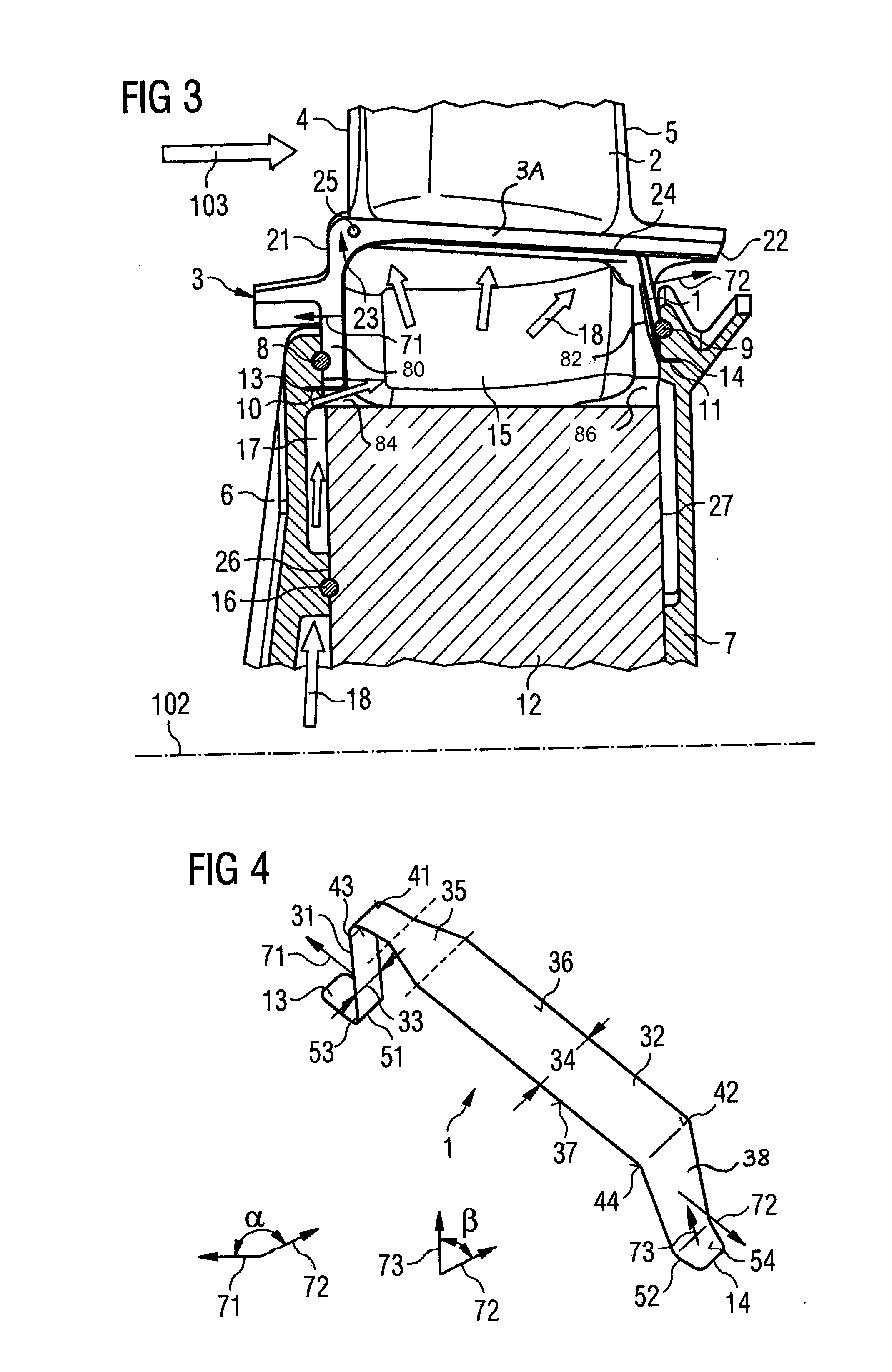
[0036]The present invention improves the sealing of turbine hot blade components. The improved sealing includes improved retention of the cooling fluid supplied to the blade under platform cavity to prevent the coolant escaping the cavity via the gap. Advantageously, more of the cooling fluid is used for better cooling the blade. The improved sealing includes preventing hot working gases ingressing the blade under platform cavity and mixing with and reducing the effectiveness of the cooling fluid. By improving the sealing also the cooling of a turbine blade can be improved. Furthermore, the amount of cooling air consumed by the turbine blades can be reduced. Moreover, the lifetime of the components is increased, leakages are reduced and the cooling air efficiency is improved. Furthermore, the part count and assembly time is reduced.

Problems solved by technology

Excessive cooling air leakage wastes valuable cooling air and has an impact on the engine efficiency.
Currently the sealing of a blade root can have up to 3 small seals to cover the two vertical joints and the one horizontal joint making them difficult to assemble and prone to leaking when all components are hot.

Method used


Image

  • Platform seal strip, turbine blade assembly and method for assembling it
  • Platform seal strip, turbine blade assembly and method for assembling it
  • Platform seal strip, turbine blade assembly and method for assembling it

Examples


Embodiment Construction

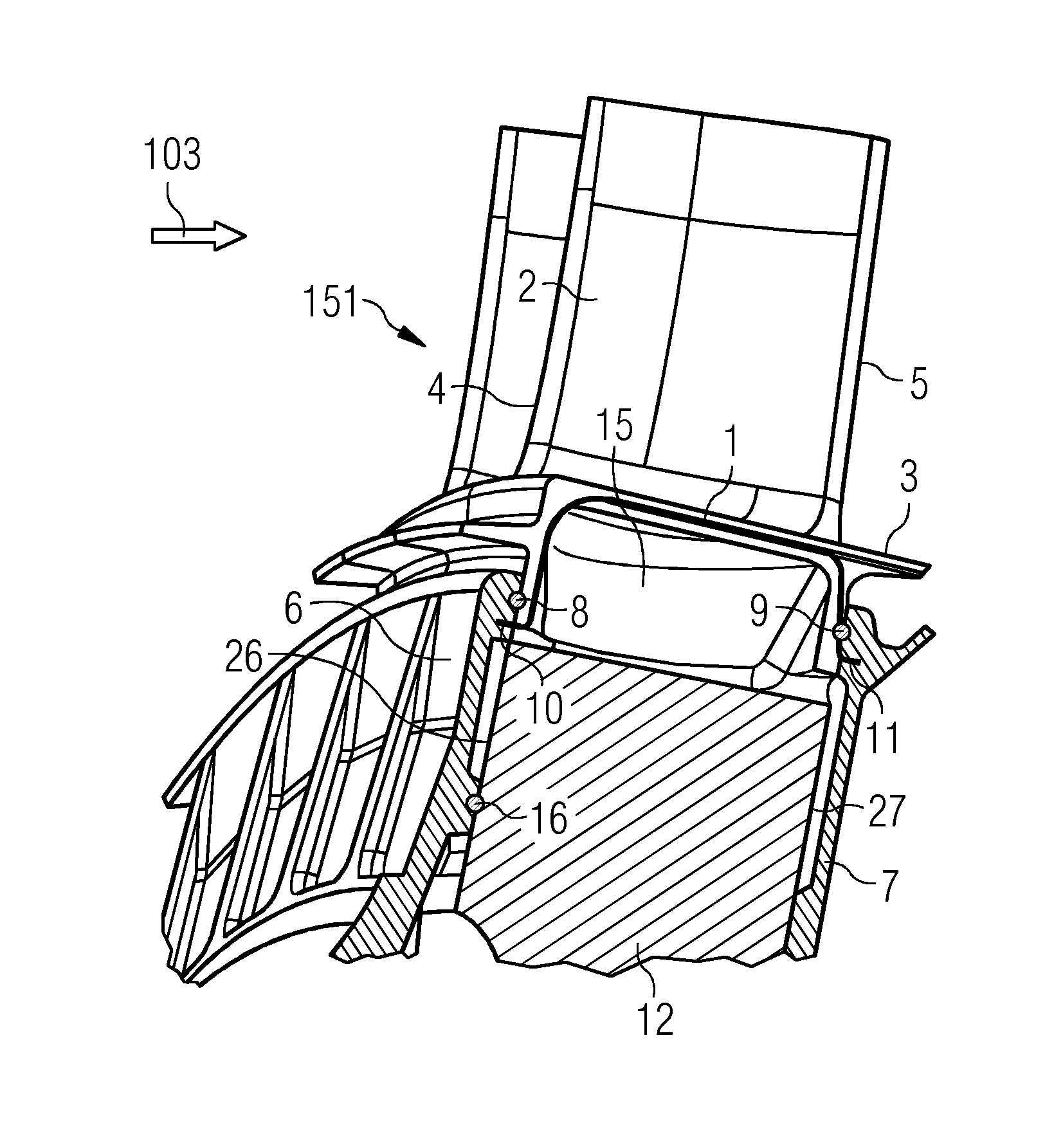
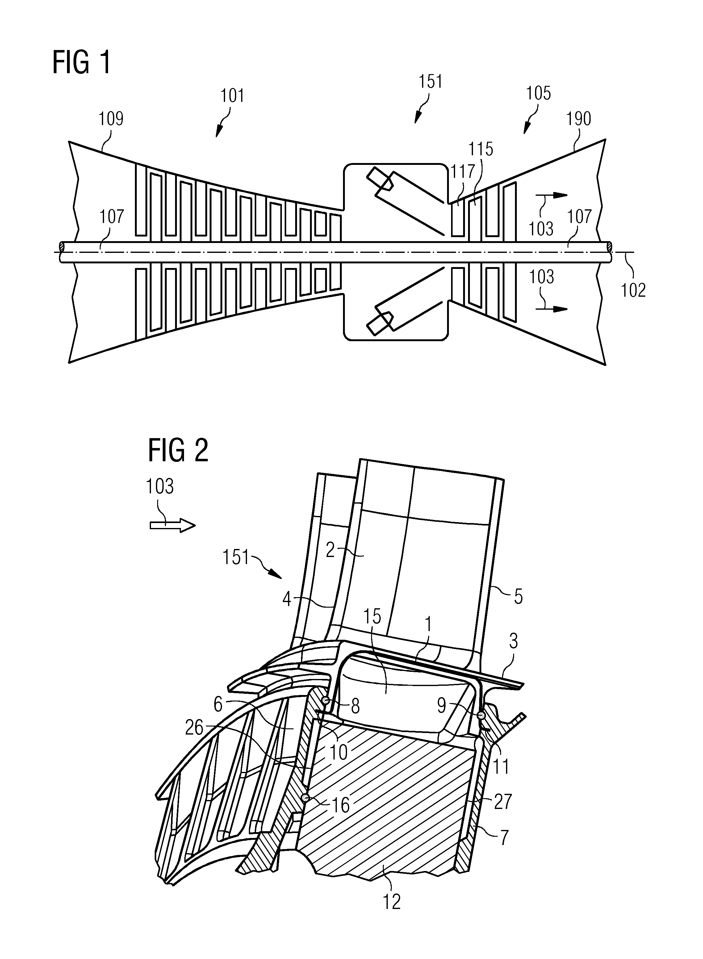
[0045]FIG. 1 schematically shows a gas turbine. A gas turbine comprises a rotation axis with a rotor. The rotor comprises a shaft 107. Along the rotor a suction portion with a casing 109, a compressor 101, a combustion portion 151, a turbine 105 and an exhaust portion with a casing 190 are located.

[0046]The combustion portion 151 communicates with a hot gas flow channel which may have a circular cross section, for example. The turbine 105 comprises a number of turbine stages. Each turbine stage comprises rings of turbine blades. In flow direction 103 of the hot gas in the hot gas flow channel a ring of turbine guide vanes 117 is followed by a ring of turbine rotor blades 115. The turbine guide vanes 117 are connected to an inner casing of a stator. The turbine rotor blades 115 are connected to the rotor. The rotor is connected to a generator, for example.

[0047]During operation of the gas turbine air is sucked and compressed by means of the compressor 101. The compressed air is led t...


PUM

PropertyMeasurementUnit
angleaaaaaaaaaa
angleaaaaaaaaaa
angleaaaaaaaaaa

Abstract

A platform seal strip, in particular for use in a gas turbine blade assembly, is provided. The platform seal strip includes an upper side, a lower side, a first portion and a second portion. The width of the first portion is smaller than the width of the second portion. The first portion and the second portion are at least partially bent downwards such that the upper side includes a convex surface portion and the lower side includes a concave surface portion.

Description

CROSS REFERENCE TO RELATED APPLICATIONS[0001]This application is the US National Stage of International Application No. PCT / EP2013 / 062115 filed Jun. 12, 2013, and claims the benefit thereof. The International Application claims the benefit of European Application No. EP12173650 filed Jun. 26, 2012. All of the applications are incorporated by reference herein in their entirety.FIELD OF INVENTION[0002]The present invention relates to a platform seal strip, a turbine blade assembly and a gas turbine. It further relates to a method for assembling a turbine blade assembly, for example a gas turbine blade assembly.BACKGROUND ART[0003]The documents EP 2 053 285 A1 and EP 2 053 286 A1 describe a seal strip with varying width that is bent at a downstream end and trapped between a blade platform and the locking plate in the assembly.[0004]In the document U.S. Pat. No. 3,918,842 a sealing member such as a wire is mounted in a groove between blade platforms of a gas turbine engine to seal betwe...

Claims


Application Information

Patent Timeline
Patent Type & Authority Applications(United States)
IPC IPC(8): F01D11/00
CPCF01D11/006F01D5/082F01D5/3015Y10T29/49321
Inventor HEADLAND, PAUL
Owner SIEMENS AG
Why Eureka
Try Eureka