

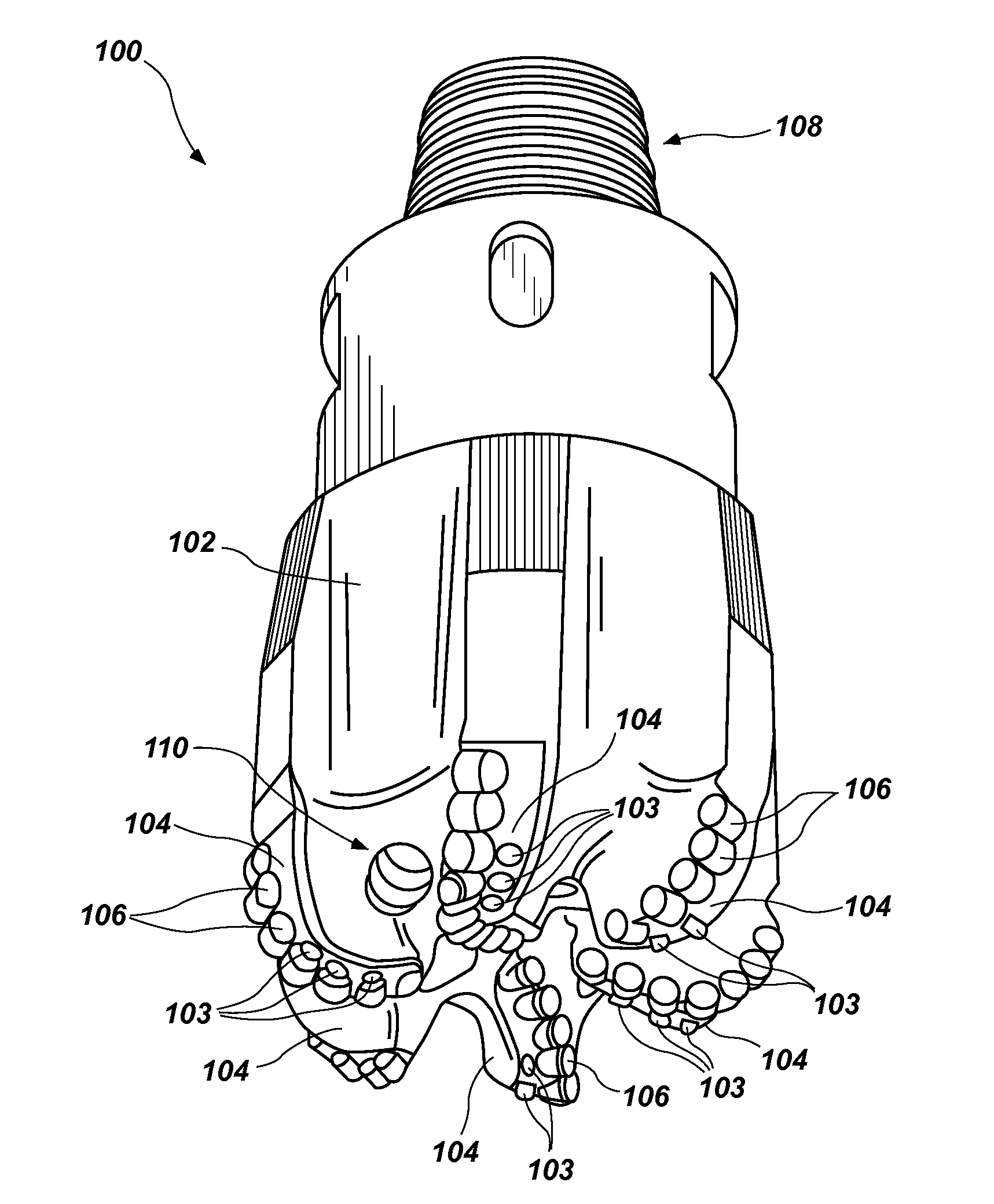
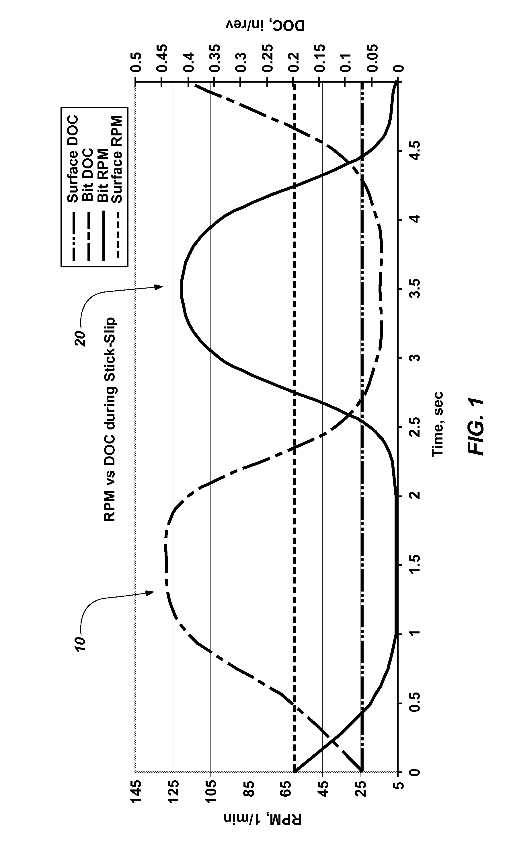
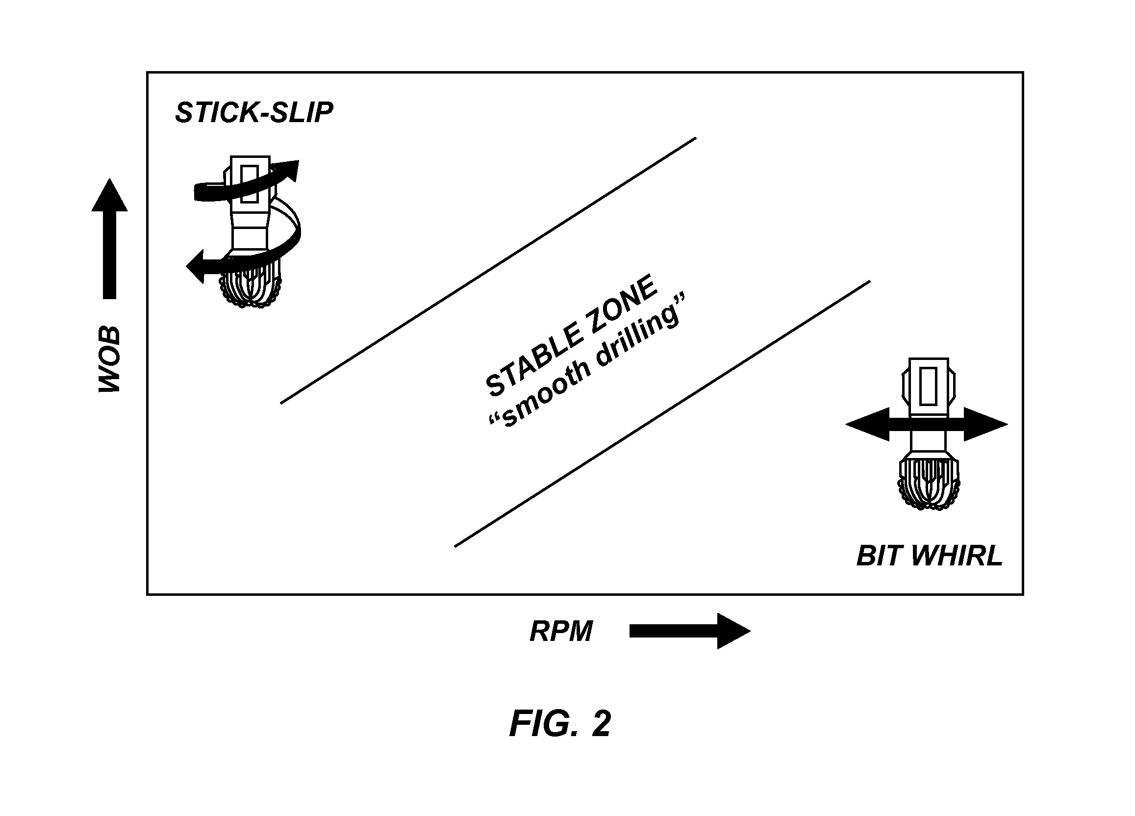
Drill bit design for mitigation of stick slip
a technology of rotary drill bits and drill bits, which is applied in the direction of cutting machines, manufacturing tools, instruments, etc., can solve the problems of bit oscillation, rapid increase of bit torque, and decrease of bit torqu
- Summary
- Abstract
- Description
- Claims
- Application Information
AI Technical Summary
Benefits of technology
Problems solved by technology
Method used
Image

Examples
embodiment 1
[0050]A method of designing an earth-boring rotary drill bit, comprising: selecting a number of blades for a bit body of the drill bit; selecting cutting elements to be mounted to the bit body of the drill bit along a cutting element profile; identifying an intended median depth-of-cut for the drill bit during drilling; designing the cutting element profile and the bit body such that an expected average rubbing area between the bit body and a subterranean formation to be drilled by the drill bit increases to a value over zero at a depth-of-cut that is about one hundred and fifty percent (150%) or less of the intended median depth-of-cut, and such that the expected average rubbing area increases with increasing depth-of-cut at an average rate of at least three square inches per inch per revolution of the drill bit (3.0 in.2 / (in. / rev)) as the depth-of-cut increases from the intended median depth-of-cut for the drill bit to about two hundred percent (200%) of the intended median depth-...
embodiment 2
[0051]The method of Embodiment 1, further comprising designing the cutting element profile and the bit body such that an expected average rubbing area between the bit body and a subterranean formation to be drilled by the drill bit is at least substantially zero at depths-of-cut equal to and below the intended median depth-of-cut.
embodiment 3
[0052]The method of Embodiment 1 or Embodiment 2, further comprising designing the cutting element profile and the bit body such that the expected average rubbing area increases to a value over zero at a depth-of-cut that is about one hundred and thirty percent (130%) or less of the intended median depth-of-cut.
PUM
 Abstract
Description
Claims
Application Information