Reconfigurable Multi-LED Light Source

a multi-led light source and reconfigurable technology, applied in the direction of electric lighting sources, lighting and heating equipment, lighting support devices, etc., can solve the problems of high cost, long time-consuming and laborious, and the cost of replacement of light sources is many times the cost of light sources

Active Publication Date: 2013-04-11
SIGNIFY HLDG BV
View PDF1 Cites 30 Cited by
  • Summary
  • Abstract
  • Description
  • Claims
  • Application Information

AI Technical Summary

Problems solved by technology

The initial cost depends on the packaging costs inherent in connecting a large number of dies to a substrate and to the power supply.
These costs are a significant fraction of the initial cost of an LED replacement for a conventional light source.
The long-term costs associated with the light source depend on the electrical conversion efficiency, the lifetime of the light source, and the cost of the replacement of the light source.
In many applications, the cost of replacement is many times the cost of the light source.
However, the increased number of LEDs also increases the packaging costs and the probability of failure due to one of the LEDs or its connections failing.

Method used


Image

  • Reconfigurable Multi-LED Light Source
  • Reconfigurable Multi-LED Light Source
  • Reconfigurable Multi-LED Light Source

Examples


Embodiment Construction

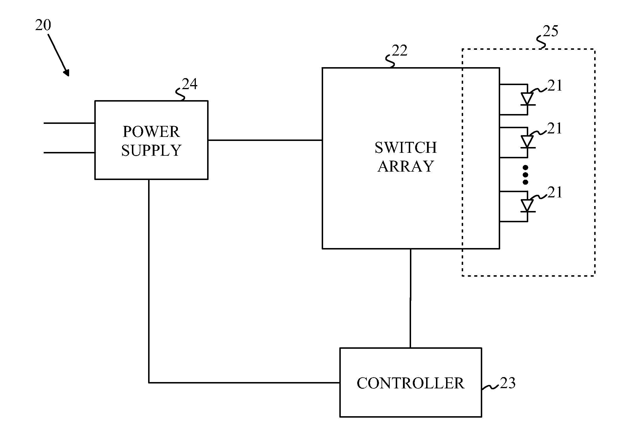
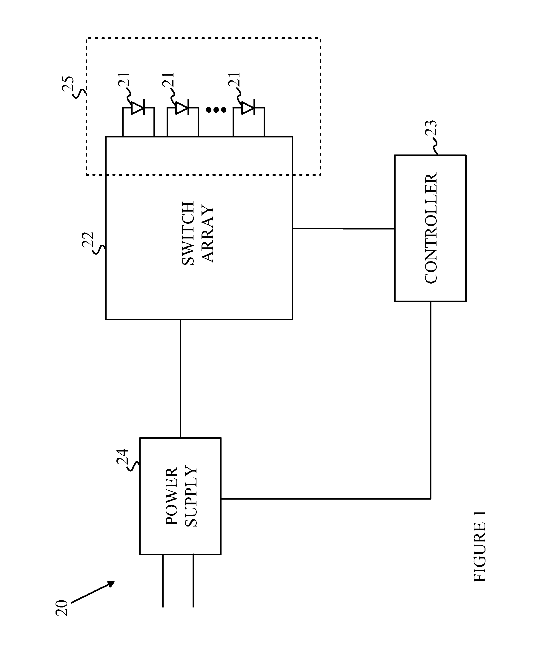
[0022]A light source according to one embodiment of the present invention includes an array of LED dies that are bonded to a substrate that includes a switching network that can be used to arrange the LEDs in various connection arrangements. Refer now to FIG. 1, which illustrates one embodiment of a light source according to the present invention. Light source 20 includes an LED array 25 having a plurality of LEDs 21 connected to a switching array 22. As will be explained in more detail below, in some embodiments an optional controller 23 configures the switches so as to arrange the LEDs in one of a plurality of different circuit configurations during the operation of the light source. The LEDs are driven from a power supply 24. The details of the switching system will be discussed in more detail below.

[0023]To simplify the following discussion, it will be assumed that all of the LEDs are identical. Each LED is characterized by two voltages. The first voltage, Vf, is the forward vol...


PUM


Abstract

A light having a plurality of LEDs and a switching substrate is disclosed. The switching substrate is coupled to LEDs and includes a plurality of switches that provide a plurality of configurations for the LEDs. Each configuration is characterized by a two-dimensional array of LEDs having a minimum bias potential and a maximum bias potential, the LED array generating light when a bias potential is provided between the power terminals that is greater than the minimum bias potential, at least two configurations being operable to provide light at bias potential within this range. The switching substrate is sub-dividable into a plurality of identical multi-LED light sources by dividing the switching substrate along predetermined lines. The array of LEDs can be organized as a nested array of LEDs. The switches can be implemented as passive switches that are set by removing portions of conductors or bridging gaps in conductors.

Description

BACKGROUND OF THE INVENTION[0001]Light-emitting diodes (LEDs) are an important class of solid-state devices that convert electric energy to light. Improvements in these devices have resulted in their use in light fixtures designed to replace conventional incandescent and fluorescent light sources. The LEDs have significantly longer lifetimes and, in some cases, significantly higher efficiency for converting electric energy to light.[0002]Most light sources that are candidates for replacement by LEDs require a plurality of LED dies to provide sufficient light to match the light output of the device being replaced. A replacement light source typically includes a plurality of LED dies, a power supply that converts AC power to DC power and some form of wiring matrix that contacts the plurality of dies in a parallel or serial configuration to the DC power source.[0003]Initial cost and electrical conversion efficiency, and replacement costs are important factors in the design of such a re...

Claims


Application Information

Patent Timeline
Patent Type & Authority Applications(United States)
IPC IPC(8): H05B37/02
CPCH05B45/48
Inventor CHAI, YANWARD, CALVIN B.
Owner SIGNIFY HLDG BV
Why Eureka
Try Eureka