Pool cleaner base plate with high pressure cleaning jets

a technology of high-pressure cleaning and pool cleaner, which is applied in the field of improved base plates for pool and tank cleaners, can solve the problems of significant materials and labor costs, in the manufacture and assembly stages, of providing multiple pressure water delivery tubes to individual water jets, and so as to reduce the problem of damage, reduce the problem of reducing the pressure of water, and eliminate the potential damage

Active Publication Date: 2013-04-18
ZODIAC POOL SYST LLC
View PDF3 Cites 12 Cited by
  • Summary
  • Abstract
  • Description
  • Claims
  • Application Information

AI Technical Summary

Benefits of technology

[0012]in an embodiment, the end and sidewalls are conveniently molded as an integral rectilinear enclosure extending transversely across the base plate with the vertical end walls positioned inside of the area in which a removable flexible mesh filter assembly and retaining mechanism is positioned. In this embodiment, the top cover member of the transverse conduit can be provided with a projecting tubular member, also most conveniently integrally molded to form a unitary assembly. The tubular member is configured to receive a conduit containing pressurized water that is delivered from a pump or other pressurized source to the interior of the transverse conduit. The source of pressurized water and the delivery conduit are preferably and advantageously positioned on the interior of the pool cleaner housing for protection so as not to be subject to mishandling or dislocation during the operation and / or transport of the pool cleaner when the exterior of the apparatus can be subjected to an impact.
[0013]As will be understood by those of ordinary skill in the art, the base plate is provided with at least one inlet opening to which water is drawn from below the apparatus and into a filter assembly which retains dirt and debris and the filtered water is discharged through an opening in the housing or through a water jet directional drive mechanism. In the embodiment in which the base plate is provided with two water inlet openings, they are typically displaced outwardly from, and on opposite sides of the longitudinal center line of the apparatus as defined by its direction of travel. With a base plate of this configuration, the water jet outlet openings are advantageously positioned in spaced relation that corresponds to the transverse positioning of the respective inlet openings, thereby providing water jets directed towards the bottom surface beneath the apparatus in general alignment with the inlet openings in order to maximize the intake of suspended dirt and debris raised by the water jet turbulence.
[0019]The configuration of the present invention in which the water jets emanate from the plane of the exterior of the base plate, solves the problem of potential damage to elements of the moving pool cleaner projecting below the base plate which contact obstacles, or even angled or sharply curved surfaces formed in the bottom of the pool, and also of such contact interfering with the programmed movement of the pool cleaner. Placing the transverse conduit inside of the pool cleaner housing and locating it on the interior surface of the base plate eliminates the potential problem of damage to the pressurized water delivery assembly by rough handling by the user and / or contact with exterior elements by those in the pool during the operation of the pool cleaning apparatus. The arrangement, location and configuration of the present invention also minimizes the problem of reducing the pressure of the water emanating from the pump by passage of the pressurized water through numerous fittings and constrictions which reduces the pressure of the water that is eventually discharged through the outlet openings in the transverse conduit. The present invention provides for more efficient operation of the water jet system, a savings in operational power costs and permits the use of a smaller pump, if desired.

Problems solved by technology

It is noted that in addition to being on the exterior of the pool cleaner, the transverse manifolds of FIG. 17 are positioned at some distance outward of the ends of the housing making them vulnerable to impact while in use in the pool and when they are placed in storage; and also locating them in a position that a user might naturally treat as a convenient handle while lifting the unit to or from the pool or carrying the unit to a storage location.
Although the various configurations and arrangements of water jets directed below the base plate disclosed in U.S. Pat. No. 7,316,751 can serve to effectively raise dirt and debris to facilitate its capture and passage through the one or more openings in the base plate for filtering, those configurations in which the high pressure water delivery tube and water jet nozzles or manifolds are on the exterior of the housing create a problem of potential damage from mishandling by the user, or contact with those in the pool with the pool cleaner, as well as damage from impact with obstacles such as pool ladders, stair steps and other obstacles that project from the pool surface or its walls.
Furthermore, the cost in materials and labor, both in the manufacture and assembly stages, associated with providing multiple pressurized water delivery tubes to individual water jets, is significant.

Method used


Image

  • Pool cleaner base plate with high pressure cleaning jets
  • Pool cleaner base plate with high pressure cleaning jets
  • Pool cleaner base plate with high pressure cleaning jets

Examples


Embodiment Construction

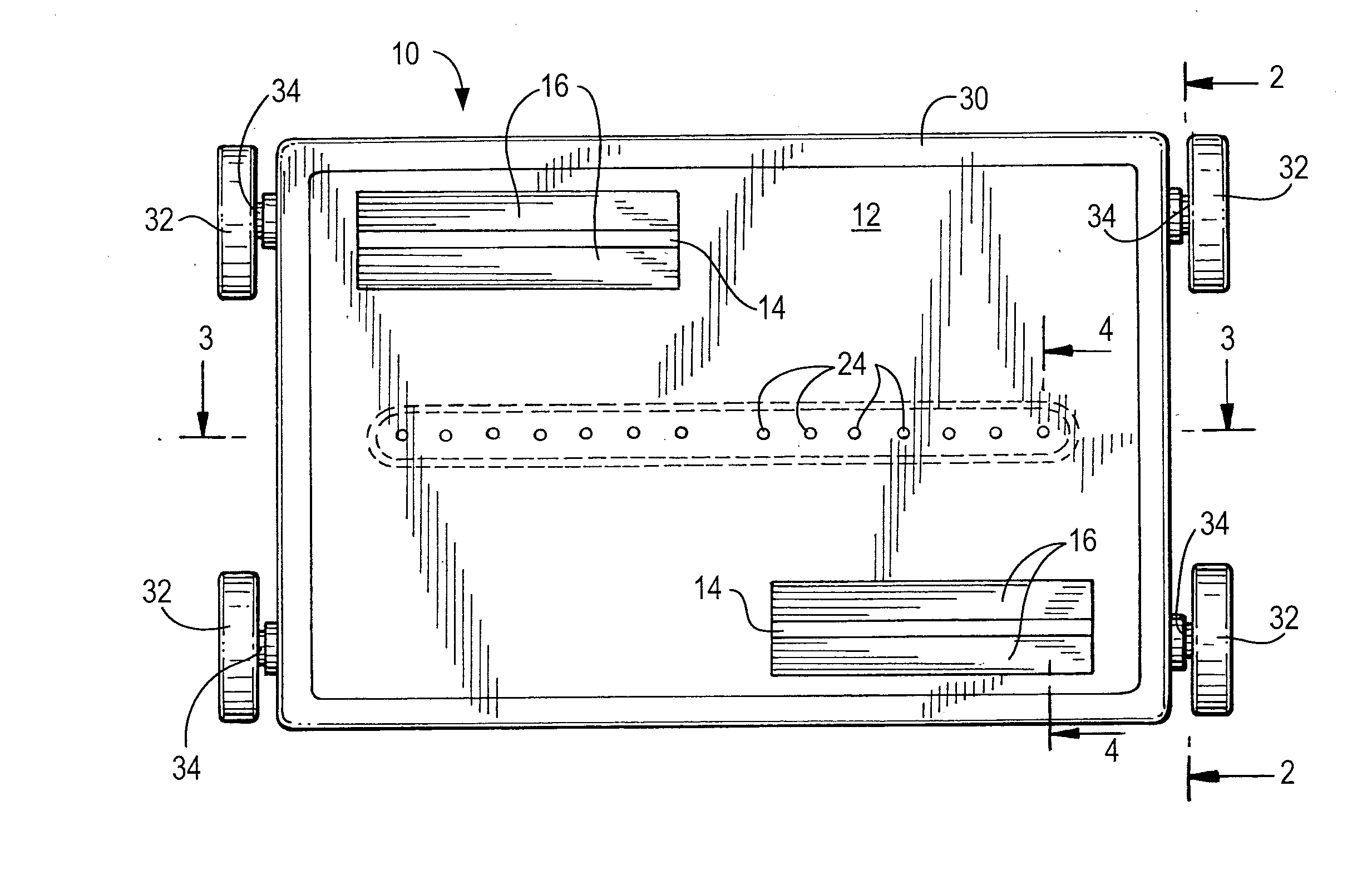
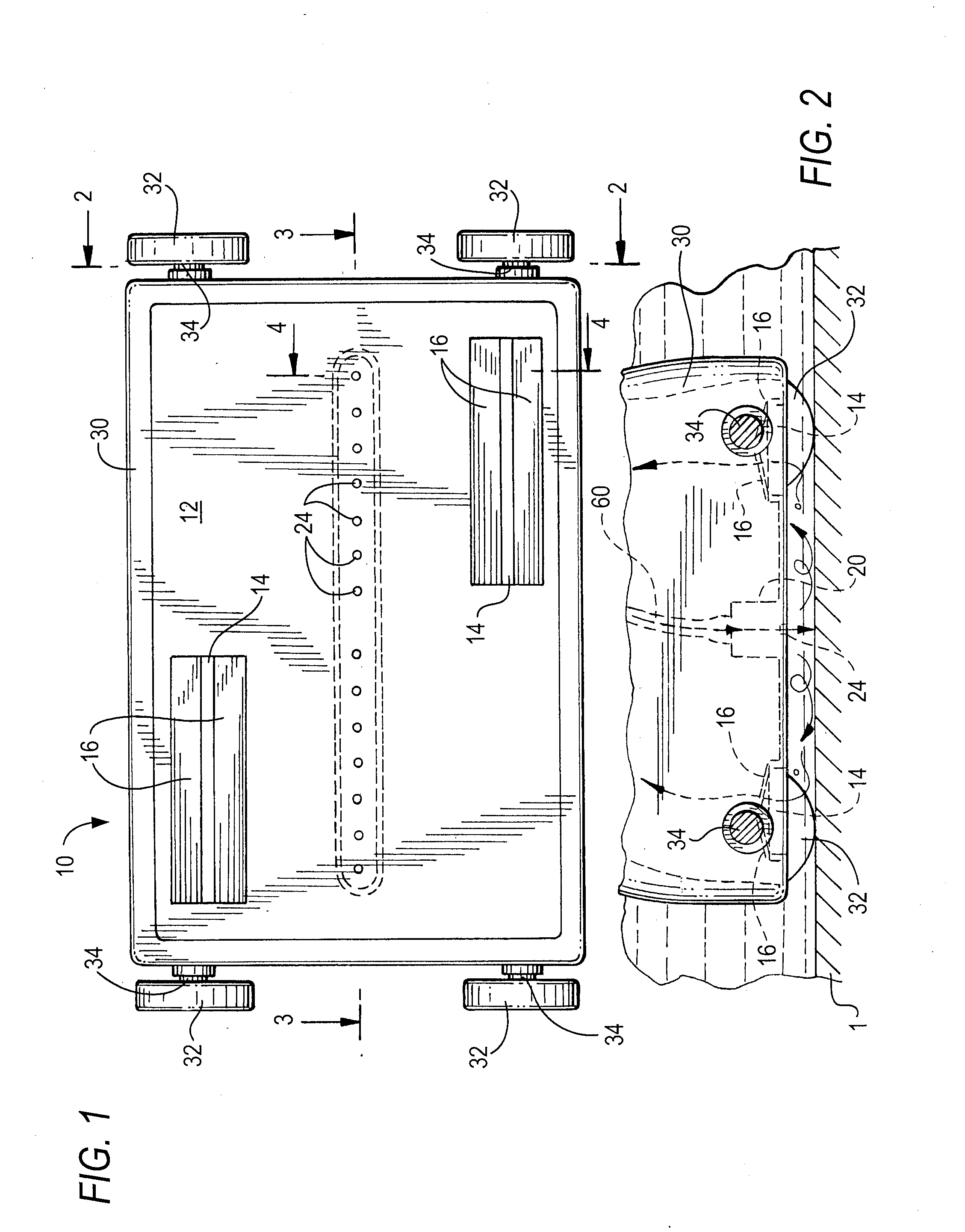
[0030]Referring to FIG. 1, a bottom view of a pool cleaning apparatus 10 that is representative of the prior art includes the base plate 12, a pair of water inlet openings 14 that are each fitted with a pair of flaps 16 that open under the influence of the low pressure created on the interior of the pool cleaner housing 30 to draw water from beneath the base plate for filtration. Flaps 30 assume a closed overlapping position to prevent dirt and debris from passing through the inlet openings 14 when the flow of water is discontinued. The pool cleaning apparatus is provided with wheels 32 mounted on transverse axles 34 at the opposing ends of the housing 30. As used herein, the term “forward” and “forward end” have reference to the direction of travel, as being understood that the pool cleaner apparatus is generally symmetrical.

[0031]With continuing reference to FIG. 1, the transverse conduit 20 which is mounted on the interior surface of the base plate 12, and shown in broken lines, ...


PUM


Abstract

The base plate of a robotic or manually propelled tank or pool cleaning apparatus includes a transverse conduit positioned on the interior surface of the base plate and is in fluid communication with a source of pressurized water that is also located within the pool cleaner's housing, which pressurized water is discharged from the bottom or lower portion of the transverse conduit through a plurality of openings that extend along a line that is transverse to the longitudinal axis of the pool cleaner's direction of travel, to produce downwardly-directed water jets that are discharged through and below the base plate towards the surface of the pool or tank over which the pool cleaning apparatus is moving to dislodge and suspend dirt and debris that is then drawn into and retained by the pool cleaner's filter.

Description

CROSS REFERENCES TO RELATED APPLICATIONS[0001]This application claims priority to co-pending provisional application 61 / 547,495 filed Oct. 14, 2011.FIELD OF THE INVENTION[0002]This invention relates to an improved base plate for hand-powered and self-propelled pool and tank cleaners that draw water containing dirt and debris from the surface beneath the moving pool cleaner for entrainment in a filter.BACKGROUND OF THE INVENTION[0003]It is now well known in the art to equip robotic and other types of tank and pool cleaners with means for discharging water jets under the cleaner body that are directed toward the surface over which the cleaner is passing in order to agitate and lift debris towards one or more vacuum or low water pressure intake openings to enhance the cleaning ability of the apparatus. The suspended dirt and debris created by the water jet turbulence renders the material temporarily buoyant so that it can be drawn into the interior of the pool cleaner housing and event...

Claims


Application Information

Patent Timeline
Patent Type & Authority Applications(United States)
IPC IPC(8): B08B9/093E04H4/16
CPCB08B9/093E04H4/1636E04H4/1654E04H4/1663E04H4/1618
Inventor PORAT, JOSEPHERLICH, GIORA
Owner ZODIAC POOL SYST LLC
Why Eureka
Try Eureka