Door weatherstrip

a weather strip and door technology, applied in the field of door weather strips, can solve the problems of easy breakage in the middle, impaired rigidity of the nozzle itself, and difficulty in pouring the sealer

Active Publication Date: 2013-04-25
NISHIKAWA RUBBER
View PDF14 Cites 1 Cited by
  • Summary
  • Abstract
  • Description
  • Claims
  • Application Information

AI Technical Summary

Benefits of technology

[0015]The above mentioned seal structure prevents water from invading through the clearance surrounded by the body weatherstrip mounted to the vehicle body, the flange end surface of a first-closing door, which is closed first when the double doors are closed, and the sealing material to be mounted to the other door; on the other hand, the present invention includes an extrusion part that is mounted on the side edge of the door, which is closed first among the doors constituting the double doors, and the molded part that is integrally formed on the upper end of the extrusion part, and targets the door weatherstrip to seal between the first-closing door and the next-closing door closed thereafter, and prevents water from invading through between the first-closing door and the door weatherstrip mounted to the door in the vehicle interior.
[0017]The objective of the present invention is to provide a door weatherstrip for a vehicle that prevents water from invading through between the first-closing door and the door weatherstrip mounted by insertion into the flange of the door, and, where the sealer can be easily poured into the groove even if the insertion groove where the flange is inserted is deep.

Problems solved by technology

However, when attempting to pour the sealer into the bottom of the insertion groove, if the depth of the groove 29 is great like the insertion groove 29 on the wider portion shown in FIG. 7, a nozzle for sealer insertion does not reach the depth of the insertion groove 29, and it becomes difficult to pour the sealer.
If the nozzle is extended in order to pour the sealer deeply in the insertion groove 29, the rigidity of the nozzle itself is impaired and it becomes easily broken in the middle.

Method used


Image

  • Door weatherstrip
  • Door weatherstrip
  • Door weatherstrip

Examples


Embodiment Construction

[0035]Hereafter, the door weatherstrip in embodiments of the present invention is explained with reference to the drawings. In the drawings, the same symbols are marked in the same structural parts shown in FIG. 1 to FIG. 8, and the explanation is omitted.

[0036]FIG. 9 is a perspective view of the overall structure of a molded part 51 in the door weatherstrip as similar to FIG. 3; FIG. 10 is a front view of the molded part 51 in the door weatherstrip mounted to the right door 3 viewing from the vehicle interior as similar to FIG. 5; FIG. 11 is a cross-sectional view in a section equivalent to the E-E line in FIG. 1, and is a cross-sectional view on the D-D line in FIG. 10; and FIG. 12 shows the state where expanded the transverse part 31a1 of the wider part 31a in the sidewall 31 on the vehicle interior side constituting the insertion groove 29.

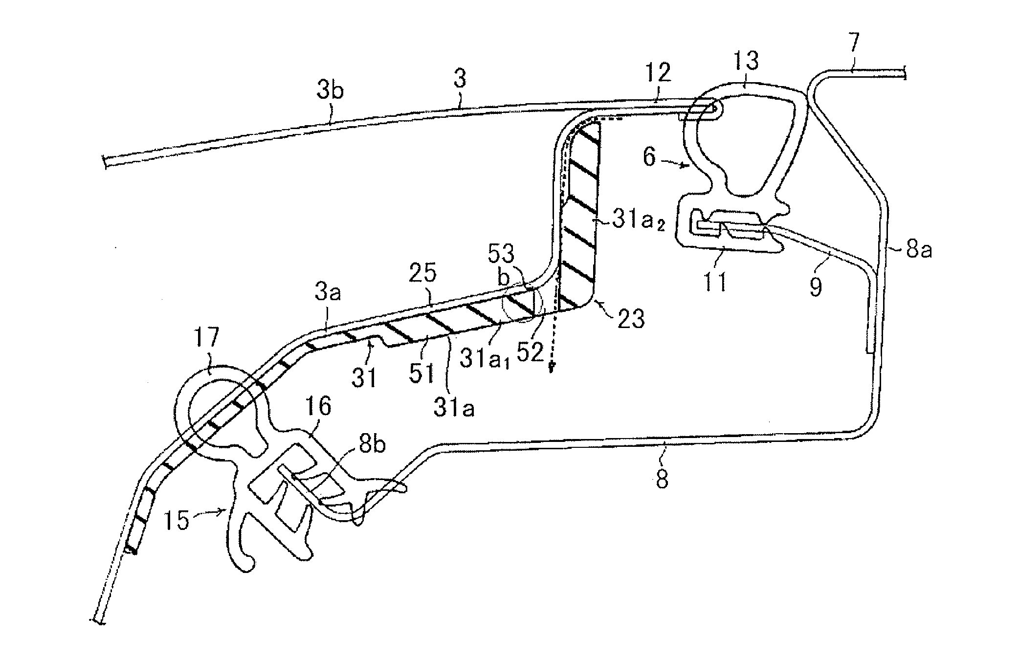
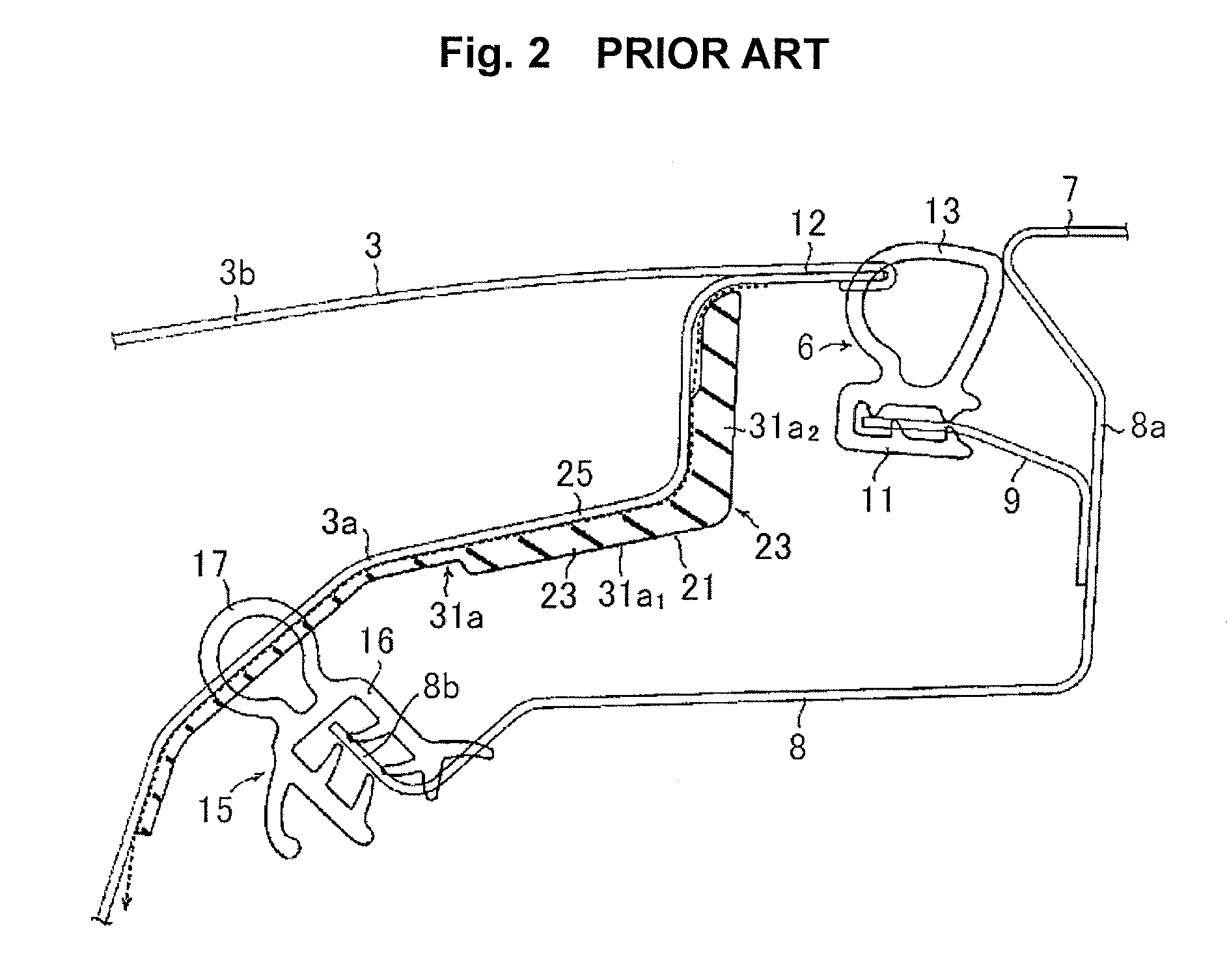
[0037]A point where the molded part 51 of the present embodiment is different from the conventional molded part 23 shown in FIG. 2 to FIG. 7 ...


PUM


Abstract

The present invention relates to a door weatherstrip for a vehicle that includes an extrusion part, which is mounted by insertion into a flange 25 formed on the vertical side edge of a first-closing door 3 among the doors constituting double doors 3 and 4, and a molded part 51, which is integrally formed on the upper end of the extrusion part, and that seals between the first-closing door 3 and a next-closing door 4 when the doors 3 and 4 are closed. A molded part 51 has a wider part 31 a including a deep insertion groove 29, and a slit 52 is formed in the door width direction from the side end on the sidewall 31, and water that has invaded through between the flange 25 and the molded part 51 flows out onto a drip channel 8 established on the upper edge of the door opening of the body via the slit 52.

Description

FIELD OF THE INVENTION[0001]The present invention relates to a door weatherstrip that is mounted to either one of two double doors in order to seal around a door in a vehicle including double doors. Furthermore, the vertical direction in the present specification means a direction relative to a vehicle, and the horizontal direction means a direction in the case of viewing the rear part of the vehicle from the rear side of the vehicle.BACKGROUND OF THE INVENTION[0002]FIG. 1 shows a vehicle including double rear doors, and the illustrated rear doors include a right door 3 that is turnably connected to the right edge of a door opening edge 1 formed on the rear surface of the vehicle body by hinges 2, and that opens / closes the right section of the door opening edge 1, and a left door 4 that is turnably connected to the left edge of the door opening edge 1 similarly by the hinges 2, and that opens / closes the left section of the door opening edge 1, and when closing the doors, after eithe...

Claims


Application Information

Patent Timeline
Patent Type & Authority Applications(United States)
IPC IPC(8): E06B7/22
CPCB60J5/105B60J10/085B60J10/86
Inventor FUKUDA, KAZUAKI
Owner NISHIKAWA RUBBER
Why Eureka
Try Eureka