
Monitoring device, and program

a monitoring device and program technology, applied in the field of monitoring devices, can solve the problems of difficult adjustment of the range sensor to properly set, inability to automatically set up the region to be monitored on the bed, etc., and achieve the effect of accurately and reproducibly detecting the movement of the person

Inactive Publication Date: 2013-04-25
PANASONIC INTELLECTUAL PROPERTY MANAGEMENT CO LTD
View PDF3 Cites 30 Cited by
  • Summary
  • Abstract
  • Description
  • Claims
  • Application Information

AI Technical Summary

Benefits of technology

The present invention allows for automatic detection of a person's movement on a bed. This enables accurate and consistent detection of a person's movement and helps to clearly delimit the area inside and outside the bed.

Problems solved by technology

However, although Japanese Patent Application Publication No. 2003-290154 discloses that the region to be monitored is installed over the bed, it is not specifically described how to set up the region to be monitored.
That is, it is impossible to automatically set up the region to be monitored on the bed.
In particular, when the range sensor is movable using the stand, it is not easy to adjust the range sensor to properly set up the object points.

Method used


Image

  • Monitoring device, and program
  • Monitoring device, and program
  • Monitoring device, and program

Examples


Embodiment Construction

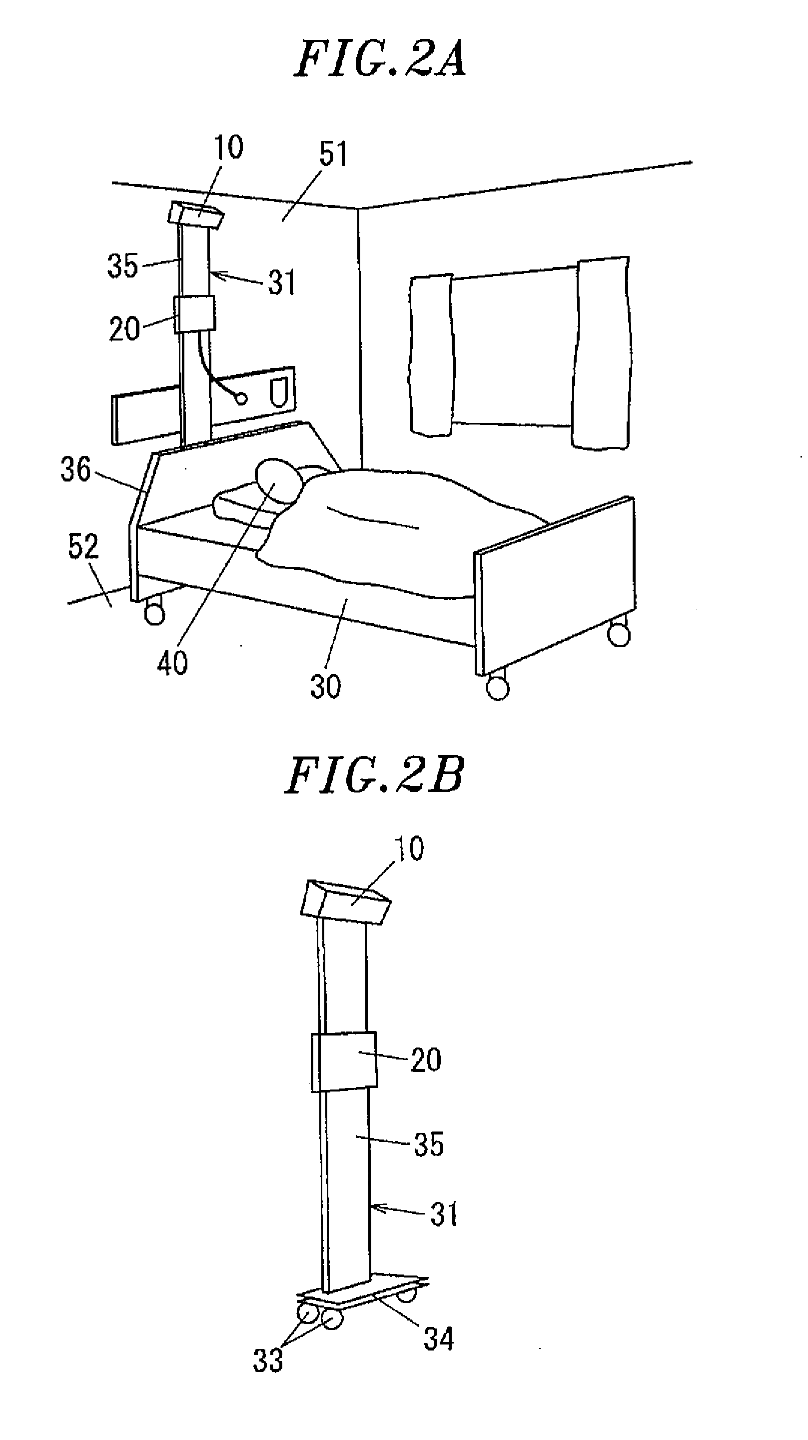
[0063]Hereinafter, the entire configuration of a monitoring device will be described. In the monitoring device of this embodiment, a range imaging sensor 10 is used to take a range image, wherein the entirety of a bed 30 is included in a field of vision of the range imaging sensor, as shown in FIGS. 2A and 2B. The range image is an image having pixel values being distance values. A variety of techniques for generating the range image have been known.

[0064]For example, as a passive range imaging sensor, a stereo imaging technique for obtaining a distance to an object based on parallax of imaging devices, has been known. Also, as an active range imaging sensor, a light sectioning technique for obtaining a distance to an object based on a triangulation principle, a time-of-flight technique for measuring a time until light reflected from an object is received after being projected, and the like have been widely employed. A range imaging sensor for obtaining a three-dimensional shape of ...


PUM


Abstract

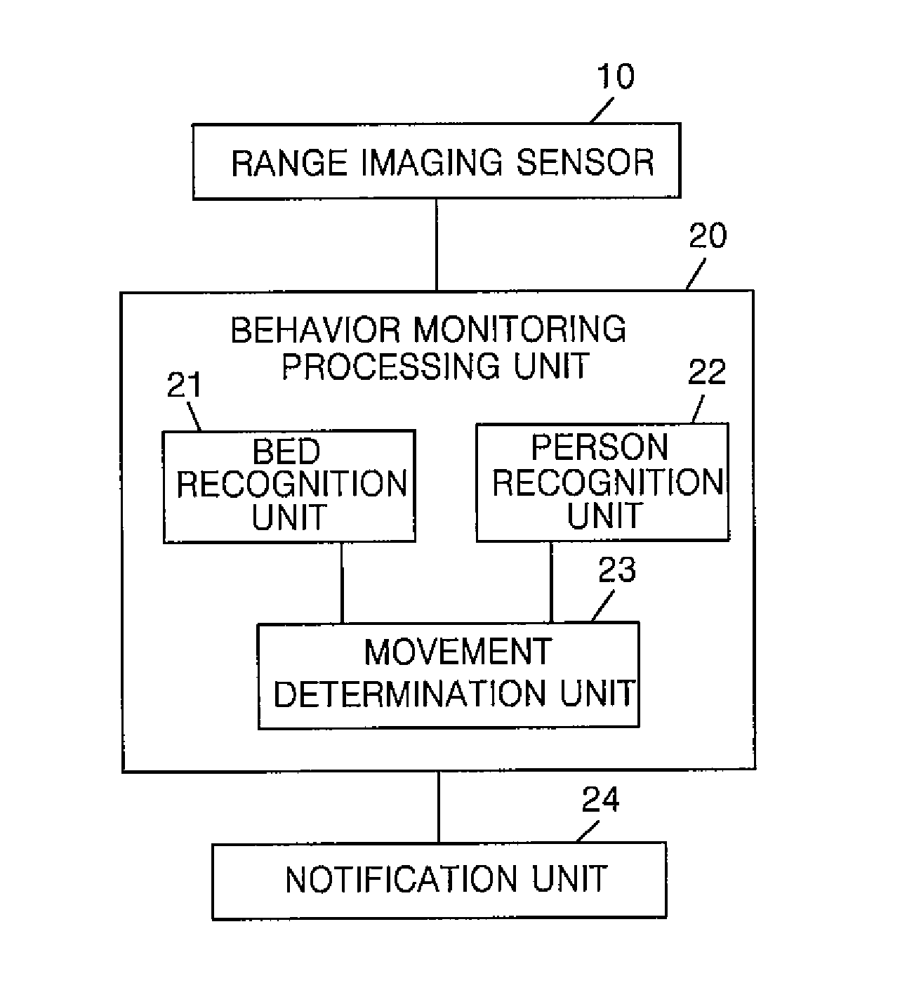
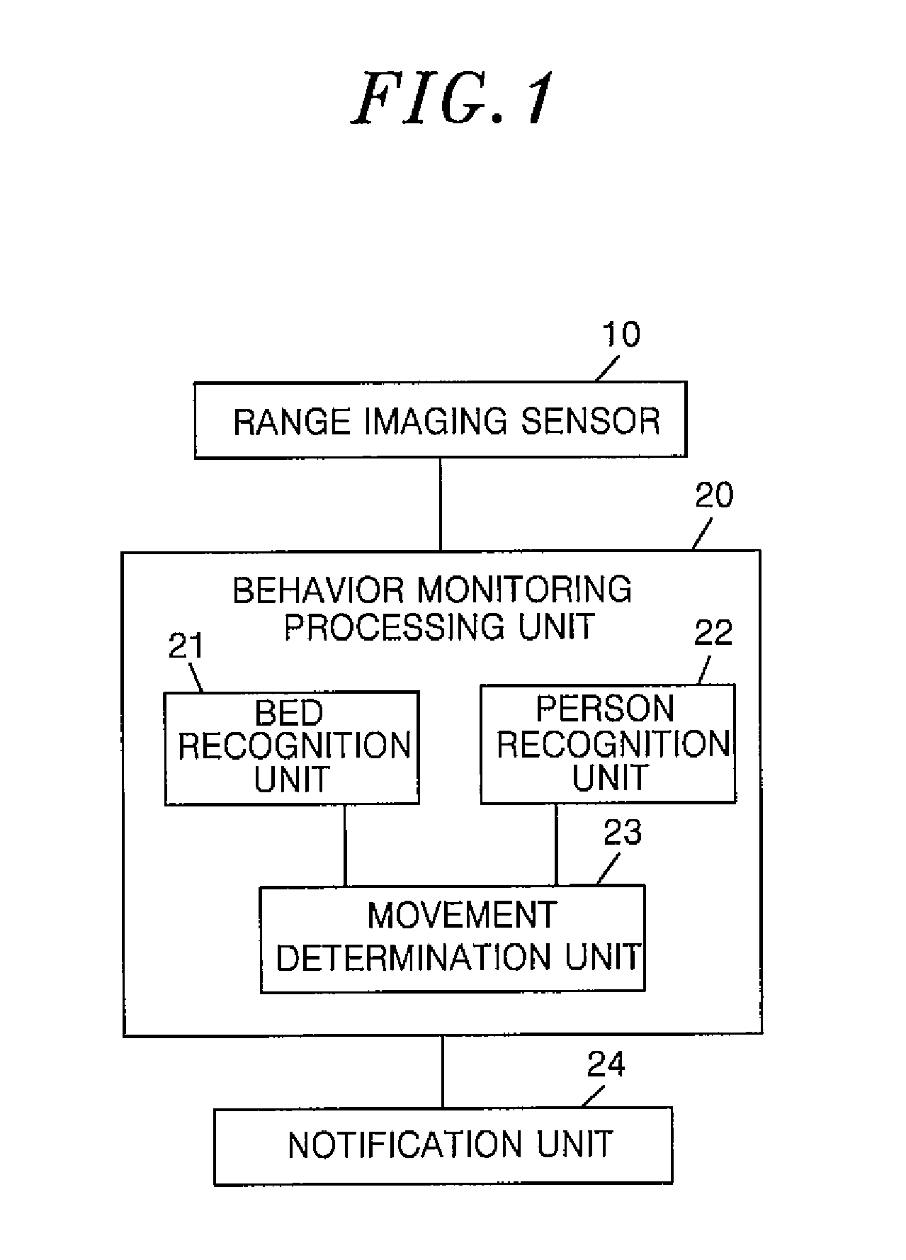
A monitoring device includes a range imaging sensor, a bed recognition unit, a person recognition unit, a movement determination unit and a notification unit. The range imaging sensor generates a range image wherein pixel values are distance values to an object, the entirety of a bed to be monitored being included in a field of vision thereof. The bed recognition unit extracts a location of the bed using the range image. The person recognition unit detects regions occupied by a person inside and outside of the range of the bed recognized by the bed recognition unit in the range image. The movement determination unit determines the movement of the person relative to the bed using a combination of the regions of the bed detected by the bed recognition unit and the person detected by the person recognition unit. The notification unit notifies a determination result of the movement determination unit.

Description

FIELD OF THE INVENTION[0001]The present invention relates to a monitoring device for monitoring a person on a bed, and a program for implementing functions used in the monitoring device in a computer.BACKGROUND OF THE INVENTION[0002]As such a monitoring device, there has been suggested a technique of obtaining a distance related value corresponding to a distance to an object to be monitored and comparing the distance related value with a threshold value to detect movement or breath of a sleeper on a bed (see, e.g., Japanese Patent Application Publication No. 2003-290154). Described in Japanese Patent Application Publication No. 2003-290154 is a technique, in which when an image change of a sleeper is not detected for a predetermined time, the object to be monitored is determined to be out of a region to be monitored, thereby detecting the object leaving the bed.[0003]In Japanese Patent Application Publication No. 2003-290154, object points including a portion of the sleeper on the b...

Claims


Application Information

Patent Timeline
Patent Type & Authority Applications(United States)
IPC IPC(8): H04N7/18
CPCA61B5/1113H04N7/18A61B5/1128A61B5/1117G08B21/0461G08B21/043
Inventor FUJII, HIROYUKINAKAMOTO, EIJI
Owner PANASONIC INTELLECTUAL PROPERTY MANAGEMENT CO LTD
Learn More