
Wireless physiological monitoring system

a physiological monitoring and wireless technology, applied in the field of wireless physiological monitoring systems, can solve the problems of limiting the mobility of patients, many cables being connected, and uncomfortable for patients, and achieve the effects of improving signal quality, and reducing the number of cables

Inactive Publication Date: 2005-11-24
EXCEL TECH
View PDF22 Cites 215 Cited by
  • Summary
  • Abstract
  • Description
  • Claims
  • Application Information

AI Technical Summary

Benefits of technology

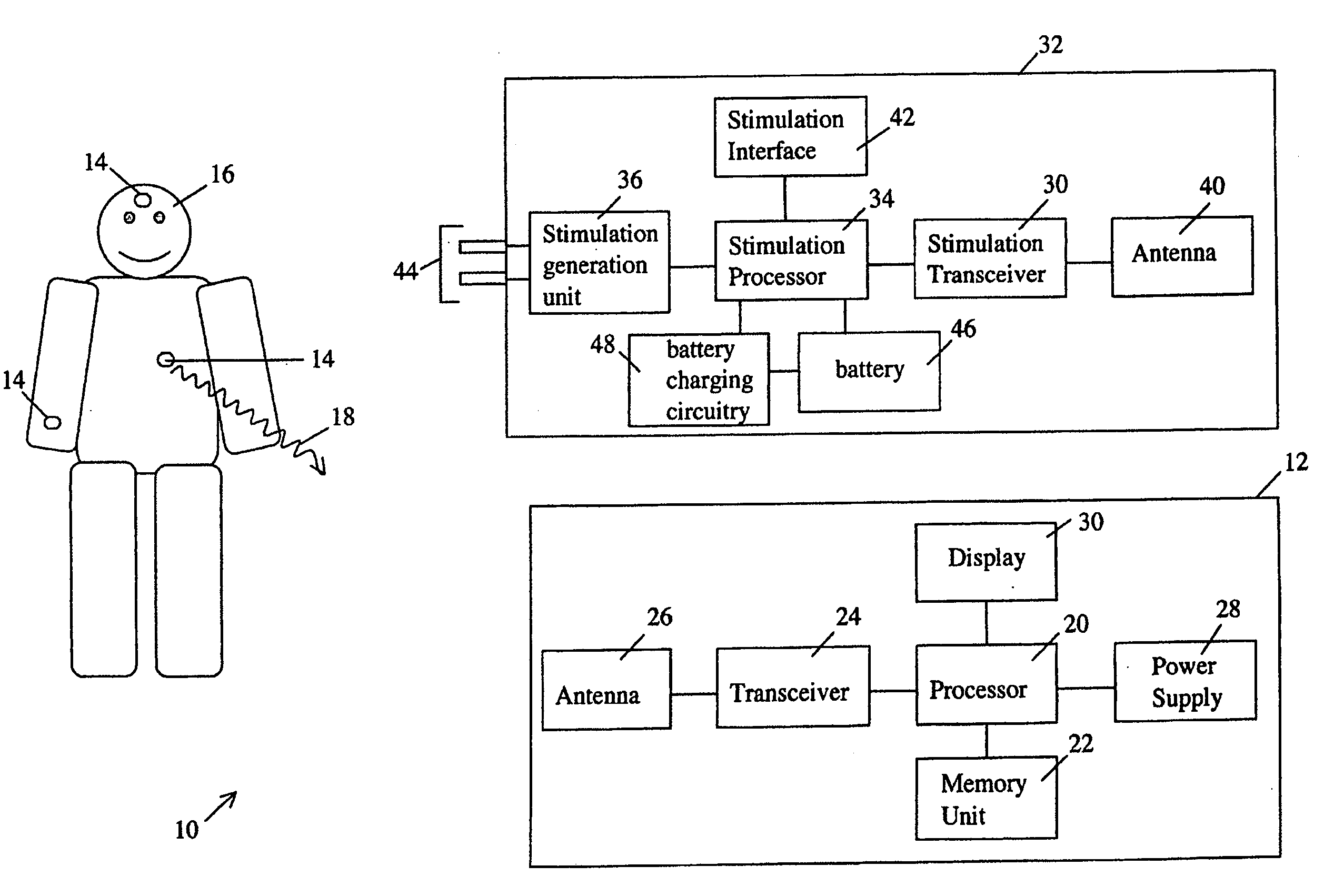
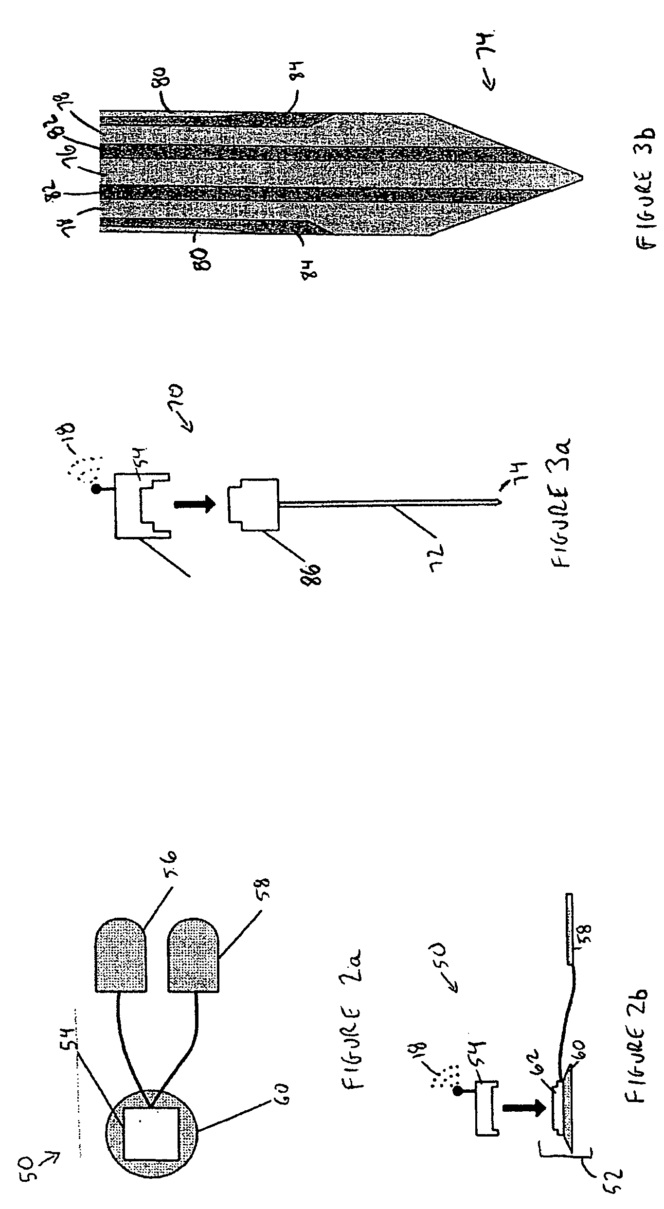
[0007] In one instance, the wireless sensor may be a wireless surface electrode assembly. In another instance, the wireless sensor may be a wireless needle assembly. In both cases, the sensors preferably include electrical leads for obtaining active, reference and common voltage measurements. This results in better signal quality for the measured physiological signals since the common mode voltage can be measured and removed from both the measured active and reference voltages. The wireless needle assembly is also advantageous in that it requires no external surface electrodes to operate.
[0011] The wireless physiological monitoring system of the invention advantageously allows for faster application and removal of the sensors to a patient since there are no cables that need to be attached. When the wireless needle assembly is used as the wireless sensor, the medical practitioner simply places the needle assembly into the recording site and receives high quality signals through the wireless connection without the need to prepare and “wire-up” the patient. The wireless physiological monitoring system provides better signal quality for the measured physiological signals since there are no cables which can pick up electromagnetic interference; this is a common problem with conventional equipment. There is also no leakage current once the measured physiological signals have been converted to wireless signals. Furthermore, since all of the components of the wireless physiological monitoring system are totally wireless, the mobility of the patient is not compromised.

Problems solved by technology

In some cases, this can result in many cables being connected between the patient and the medical instrumentation.
The cables are uncomfortable for the patient and limit the mobility of the patient.
The cables also make it difficult to perform any tests on the patient which require the patient to move.
Further, in some cases, the cables may be stiff and can easily become detached from the patient especially when the patient moves.
The plurality of cables connecting the patient to the medical instrumentation are also cumbersome for the medical personnel that interact with the patient.
In particular, the entire set-up can be confusing and in some cases requires expertise for arranging all of the different electrodes and cables.
Accordingly, the time required for attaching or removing the electrodes and cables to or from the patient can be quite long.
This can be detrimental in situations in which speed is of the essence.
In addition, the medical personnel may accidentally trip or become entangled in the cables.
Further, in the operating room, the cables to the patient are not accessible during surgery since the cables are in the “sterile field”.
This is a problem when troubleshooting faulty cables since cables in the operating room are routinely run over by people and heavy equipment and therefore subject to a high failure rate.

Method used


Image

  • Wireless physiological monitoring system
  • Wireless physiological monitoring system
  • Wireless physiological monitoring system

Examples


Embodiment Construction

[0027] It will be appreciated that for simplicity and clarity of illustration, elements shown in the figures have not necessarily been drawn to scale. For example, the dimensions of some of the elements may be exaggerated relative to other elements for clarity. Further, where considered appropriate, reference numerals may be repeated among the figures to indicate corresponding or analogous elements. In addition, numerous specific details are set forth in order to provide a thorough understanding of the invention. However, it will be understood by those of ordinary skill in the art that the invention may be practiced without these specific details. In other instances, well-known methods, procedures and components have not been described in detail so as not to obscure the invention.

[0028] Referring first to FIG. 1, shown therein is an exemplary embodiment of a wireless physiological monitoring system 10. The wireless physiological monitoring system 10 comprises a monitoring device 12...


PUM


Abstract

Embodiments of the invention relate to a wireless physiological monitoring system. The system includes at least one wireless sensor and a monitoring device which are linked to one another of a wireless fashion for measuring physiological signals of a patient. The at least one wireless sensor is located on the patient and may comprise a wireless surface electrode assembly or a wireless needle assembly. The system may also comprise a wireless stimulator syncronized with the wireless sensor for performing certain diagnostic tests, such as nerve conduction velocity tests, for example. The wireless sensor preferably includes active, reference and common conductors. The common conductor can be used to measure the common mode voltage of the patient in the vicinity of the testing, and this voltage can then be subtracted from the measured active and reference voltages.

Description

RELATED APPLICATIONS [0001] This application claims the benefit of U.S. Provisional Patent Application Ser. No. 60 / 571,944 filed on May 18, 2004, the entire contents of which are hereby incorporated by reference, U.S. Provisional Patent Application Ser. No. 60 / 571,890, filed on May 18, 2004, the entire contents of which are hereby incorporated by reference and U.S. Provisional Patent Application Ser. No. 60 / 571,942 filed on May 18, 2004, the entire contents of which are hereby incorporated by reference.FIELD OF THE INVENTION [0002] The invention relates to a wireless physiological monitoring system that can be used to measure a wide variety of physiological signals from a patient for monitoring the patient and / or diagnosing certain medical conditions. BACKGROUND OF THE INVENTION [0003] The measurement of physiological signals from a patient for monitoring the patient and / or diagnosing a particular medical condition conventionally requires medical instrumentation to be physically att...

Claims


Application Information

Patent Timeline
Patent Type & Authority Applications(United States)
IPC IPC(8): A61B5/00A61N1/04A61N1/36
CPCA61B5/0002A61N1/0456A61N1/36017A61N1/36014A61N1/0502A61B5/4041
Inventor MUMFORD, JOHN ROBERTKURTZ, RONALD LEON
Owner EXCEL TECH
Learn More