Input apparatus

Active Publication Date: 2013-05-16
KYOCERA CORP
View PDF1 Cites 123 Cited by
  • Summary
  • Abstract
  • Description
  • Claims
  • Application Information

AI Technical Summary

Benefits of technology

[0037]According to the present invention, the input apparatus for detecting the contact to the touch sensor

Problems solved by technology

Therefore, the operator may not be able to obtain feedback in response to an operation to the touch sensor.
Since the operator may not be able to obtain an operation sensation “having pressed or released pressing” upon the operation, the operator may not be able to confirm about whether the operation is appropriately detected by the terminal.
In using such a terminal, accordingly, the operator is likely to perform a repetitious operation by repeatedly touching the same position, w

Method used


Image

  • Input apparatus
  • Input apparatus
  • Input apparatus

Examples


first embodiment

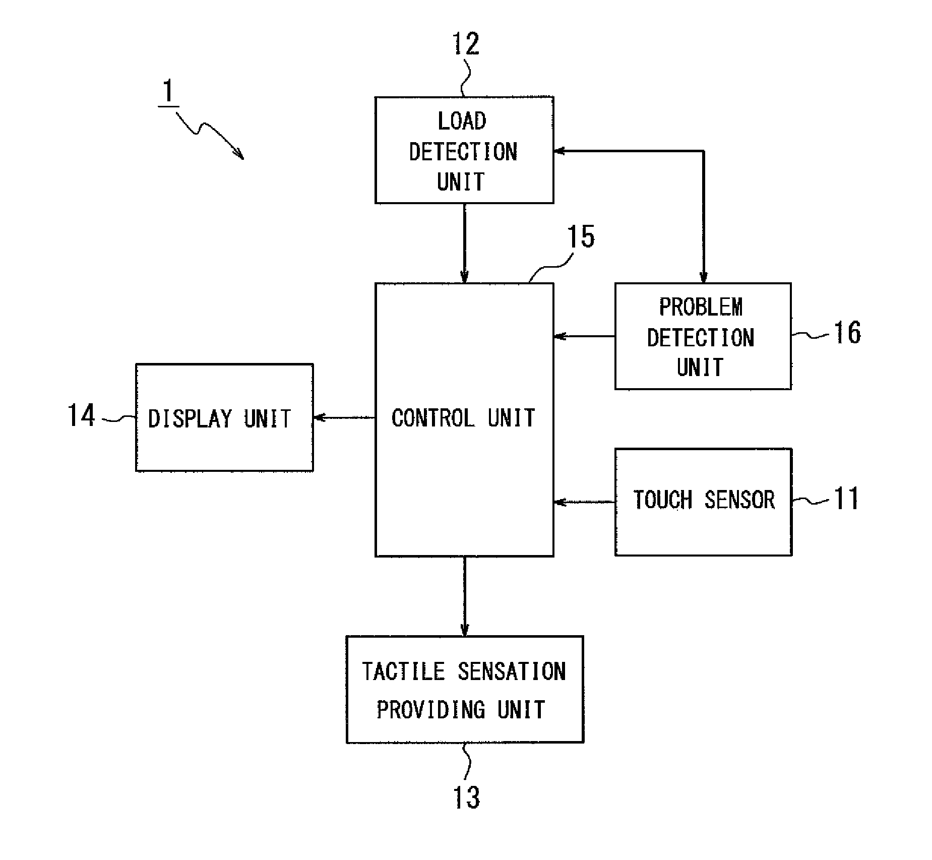
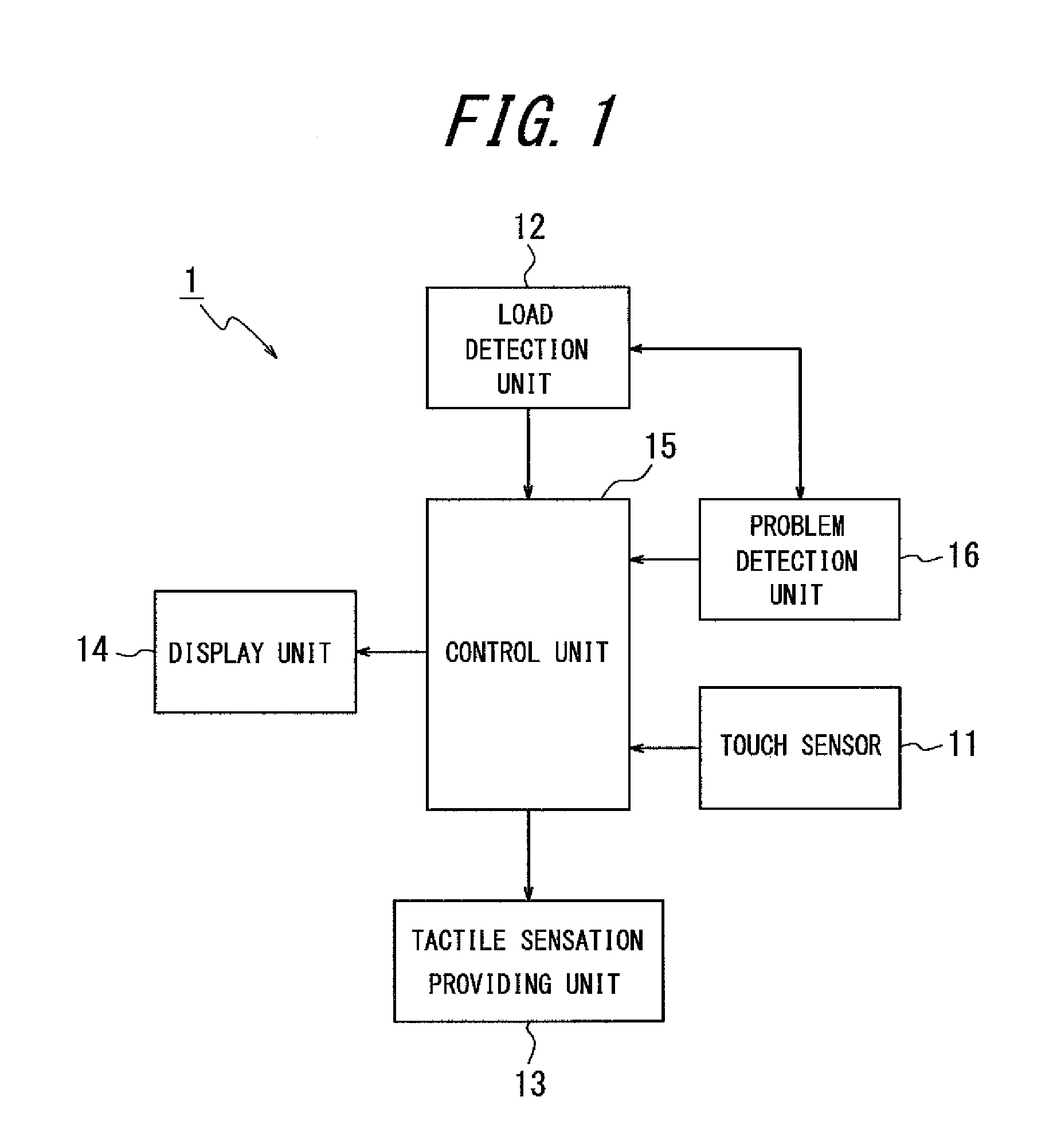
[0048]FIG. 1 is a functional block diagram illustrating a schematic configuration of an input apparatus according to a first embodiment of the present invention. According to the present embodiment, any input apparatus is applicable, as long as it receives an operator's operation by using a touch sensor. Such an input apparatus may be, for example, an input apparatus for inputting characters and numbers to mobile terminals or an input apparatus used for an ATM machine at a bank or for a ticket vending machine at a train station.

[0049]As illustrated in FIG. 1, an input apparatus 1 according to the present embodiment includes a touch sensor 11, a load detection unit 12, a tactile sensation providing unit 13, a display unit 14, a control unit 15 and a problem detection unit 16.

[0050]The touch sensor 11 is usually disposed on a front face of the display unit 14 such that a touch face of the touch sensor 11 detects a contact to an object such as a key and a button (hereinafter, referred ...

second embodiment

[0091]Next, an input apparatus according to a second embodiment of the present invention will be described. An input apparatus 2 according to the second embodiment may have a configuration similar to that of the input apparatus 1 described in the first embodiment, although the operation by the control unit 15 described in the first embodiment is partially altered. Hence, the same descriptions as those of the first embodiment will be omitted appropriately.

[0092]The second embodiment is applicable when the input apparatus 1 according to the first embodiment receives input of a plurality of levels relative to the pressure load such as, for example, a shutter button of a camera. That is, the input apparatus 2 according to the second embodiment may receive inputs of a plurality of levels by changing the operations performed in the “haptic input mode” and the “touch panel input mode” described in the first embodiment with reference to FIG. 5 and FIG. 6.

[0093]First, an operation in the “ha...


PUM


Abstract

While detecting a contact as well as a pressure load to a touch sensor, to deal with a problem of the pressure load detection, an input apparatus 1 includes a touch sensor 11, a load detection unit 12 for detecting the pressure load on the touch sensor 11, a problem detection unit 16 for detecting the problem with the load detection unit 12, and a control unit 15 for controlling switchover between a first input mode for performing a predetermined operation when the touch sensor 11 detects the contact and a second input mode for performing the predetermined operation when the load detection unit 12 detects a pressure load satisfying a predetermined standard load while the touch sensor 11 is detecting the contact. The control unit 15, when the problem detection unit 16 detects the problem with the load detection unit 12, prevents switching to the second mode.

Description

CROSS REFERENCE TO RELATED APPLICATION[0001]This application claims priority to and the benefit of Japanese Patent Application No. 2010-169828 filed on Jul. 28, 2010, the entire contents of which are incorporated herein by reference.TECHNICAL FIELD[0002]The present invention relates to an input apparatus for detecting a contact to a touch sensor.BACKGROUND ART[0003]In recent years, there are mobile terminals such as mobile phones that employ input apparatuses having touch sensors such as touch panels, touch switches, or the like, as input apparatuses such as operation units, switches and the like configured to detect operations by operators. Such input apparatuses having touch sensors are popularly employed not only by the mobile terminals but also by information equipments such as calculators, ticket vending machines, home electric appliances such as microwaves, TV sets, lighting equipments, industrial equipments (FA equipments) and the like.[0004]There are known a variety of types...

Claims


Application Information

Patent Timeline
IPC IPC(8): G06F3/041
CPCG06F3/041G09G2330/12G06F2203/04106G06F3/0414G06F3/016
Inventor FURUKAWA, TAKASHI
Owner KYOCERA CORP
Why Eureka
Try Eureka