Input apparatus and control method for input apparatus

a control method and input apparatus technology, applied in the direction of instruments, computing, electric digital data processing, etc., can solve the problems of difficult to confirm auditory feedback, stress for the operator, and the inability of the operator to obtain feedback to the input, so as to reduce the number of components and the cost, save space for the components, and reduce the size of the apparatus

Active Publication Date: 2012-06-21
KYOCERA CORP
View PDF5 Cites 31 Cited by
  • Summary
  • Abstract
  • Description
  • Claims
  • Application Information

AI Technical Summary

Benefits of technology

[0022]The input apparatus according to the present invention, utilizing direct piezoelectric effect and converse piezoelectric effect of the piezoelectric element, uses the piezoelectric element as a load sensor to detect the pressure load on the touch face of the to

Problems solved by technology

Since the touch sensors themselves are not physically displaced when touched, an operator cannot obtain feedback to an input even though the touch input is received.
As a result, the operator is likely to input erroneously by touching the same spot multiple times, which may be stressful for the operator.
However, such auditory feedback may be difficult to be confirmed in

Method used


Image

  • Input apparatus and control method for input apparatus
  • Input apparatus and control method for input apparatus
  • Input apparatus and control method for input apparatus

Examples


Embodiment Construction

[0026]An embodiment of the present invention will be described with reference to the accompanying drawings.

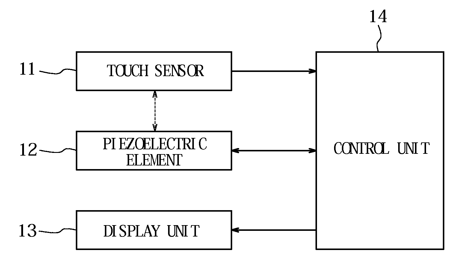
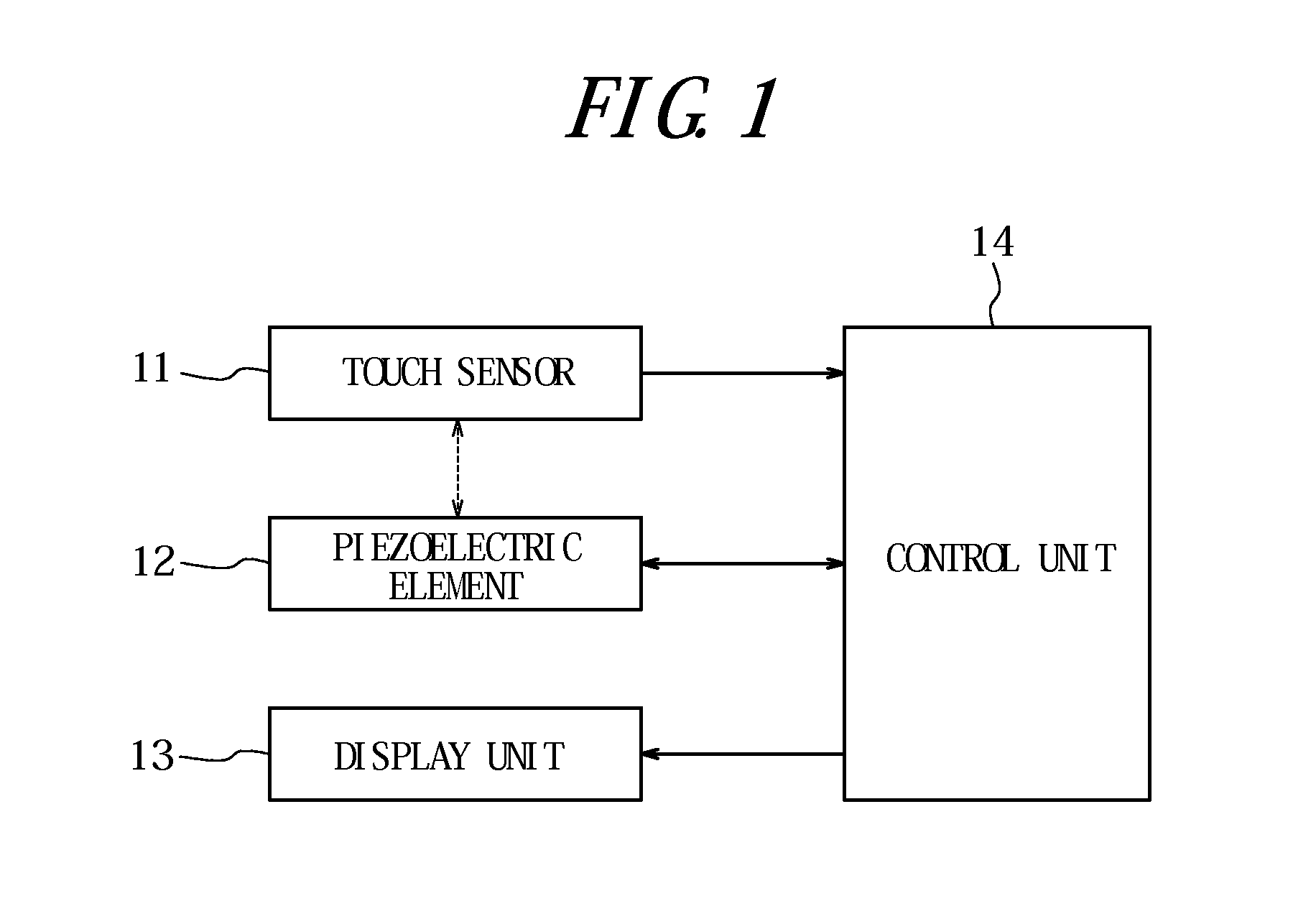
[0027]FIG. 1 is a functional block diagram illustrating a schematic configuration of an input apparatus according to one embodiment of the present invention. The input apparatus has a touch sensor 11, a piezoelectric element 12, a display unit 13, and a control unit 14 to control an operation of each unit.

[0028]Under control of the control unit 14, the touch sensor 11 detects a touch input to a touch face of the touch sensor 11 by a pressing object, such as a finger and the like, and provides the control unit 14 with position information of a touch position. The touch sensor 11 may be of a known type, such as a resistive film type, a capacitive type, an optical type and the like, and disposed on the display unit 13.

[0029]The piezoelectric element 12 is mounted on the touch sensor 11. Under control of the control unit 14, the piezoelectric element 12 is activated in one of a loa...


PUM


Abstract

An input apparatus has a touch sensor 11 configured to detect a touch input, a piezoelectric element 12 mounted on the touch sensor 11, and a control unit 15 configured to detect a pressure load on a touch face 11a of the touch sensor 11 based on an output signal of the piezoelectric element 12 and, when the pressure load detected satisfies a standard to provide a tactile sensation, to drive the piezoelectric element 12 such that the tactile sensation is provided to an object pressing the touch face 11a.

Description

CROSS REFERENCE TO RELATED APPLICATION[0001]This application claims priority to and the benefit of Japanese Patent Application No. 2009-197132 filed on Aug. 27, 2009, the entire contents of which are incorporated herein by reference.TECHNICAL FIELD[0002]The present invention relates to an input apparatus having a touch sensor and a control method for an input apparatus.BACKGROUND ART[0003]In recent years, input apparatus such as operation units, switches and the like having touch sensors such as touch panels, touch switches and the like to receive input operations by users have been widely used for mobile terminals such as mobile phones, information equipment such as calculators and ticket vending machines, home electric appliances such as microwaves, TV sets and lighting equipment, industrial equipment (FA equipment) and the like.[0004]There are known a variety of types of those touch sensors, such as a resistive film type, a capacitive type, an optical type and the like. However, ...

Claims


Application Information

Patent Timeline
IPC IPC(8): G06F3/041
CPCG06F2203/04105G06F3/016G06F3/041G06F3/0416G06F3/04142
Inventor AONO, TOMOTAKE
Owner KYOCERA CORP
Why Eureka
Try Eureka