Liquid Ejecting Head and Liquid Ejecting Apparatus

a liquid ejecting head and liquid ejecting technology, applied in the liquid field, can solve the problems of increasing the size of the recording head, increasing the size of the flexible cable, increasing the cost, etc., and achieve the effect of reducing the size of the recording head and reducing the cos

Active Publication Date: 2013-05-16
SEIKO EPSON CORP
View PDF2 Cites 4 Cited by
  • Summary
  • Abstract
  • Description
  • Claims
  • Application Information

AI Technical Summary

Benefits of technology

[0010]An advantage of some aspects of the invention is that there is provided a liquid ejecting head configured to be capable of having a reduced size of the head and a reduced cost, and a liquid ejecting apparatus having the same.

Problems solved by technology

Therefore, there is a problem of an increase in the size of the recording head.
Therefore, there is a problem of an increase in the size of the flexible cable and an increase in cost.
In the same manner, in the latter configuration, formation of the clearance hole configured to allow passage of the supply flow channel in the wiring substrate is needed, and hence the cost is increased in association with increase in the size of the wiring substrate in this aspect as well.

Method used


Image

  • Liquid Ejecting Head and Liquid Ejecting Apparatus
  • Liquid Ejecting Head and Liquid Ejecting Apparatus
  • Liquid Ejecting Head and Liquid Ejecting Apparatus

Examples


Embodiment Construction

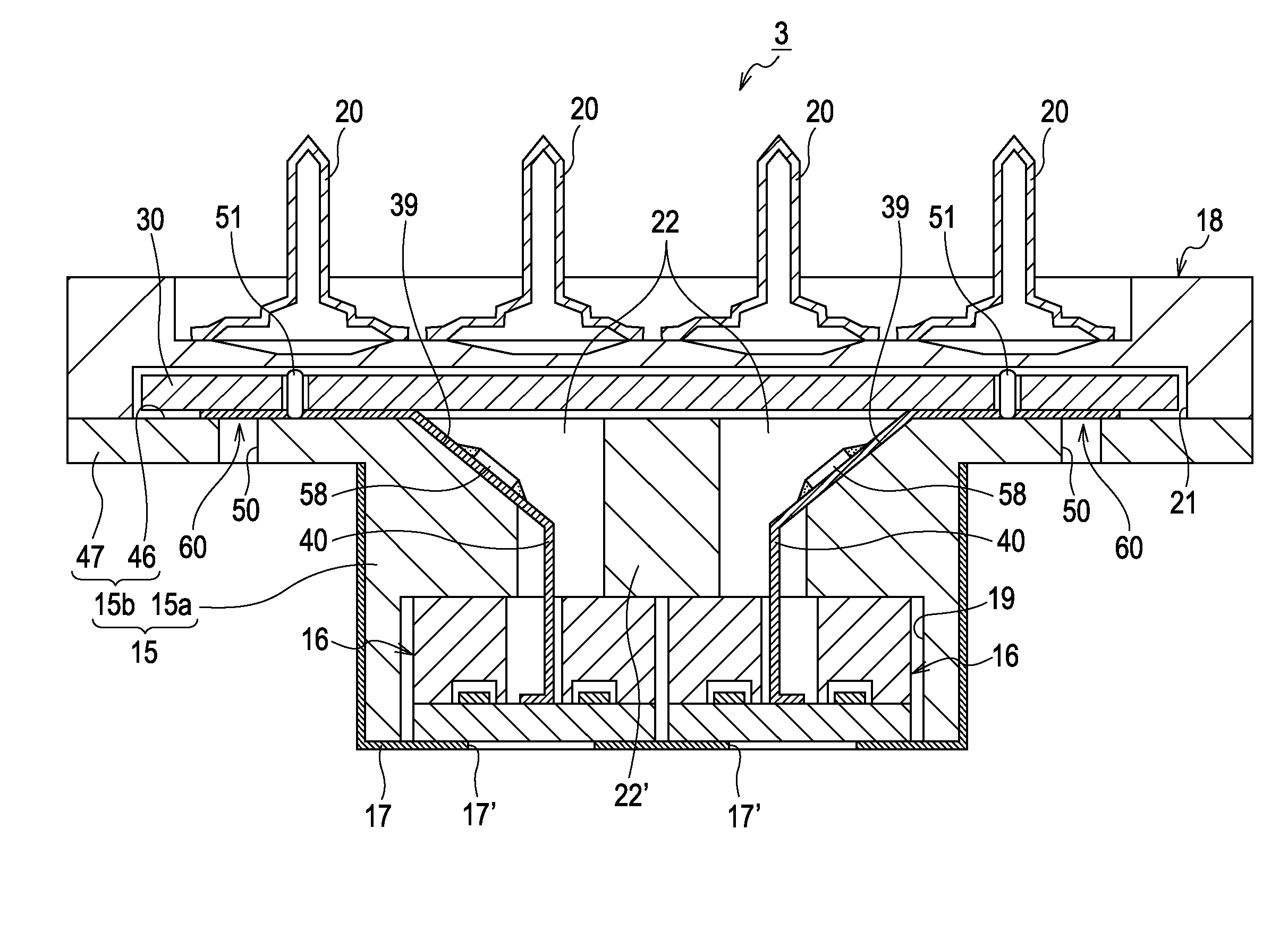
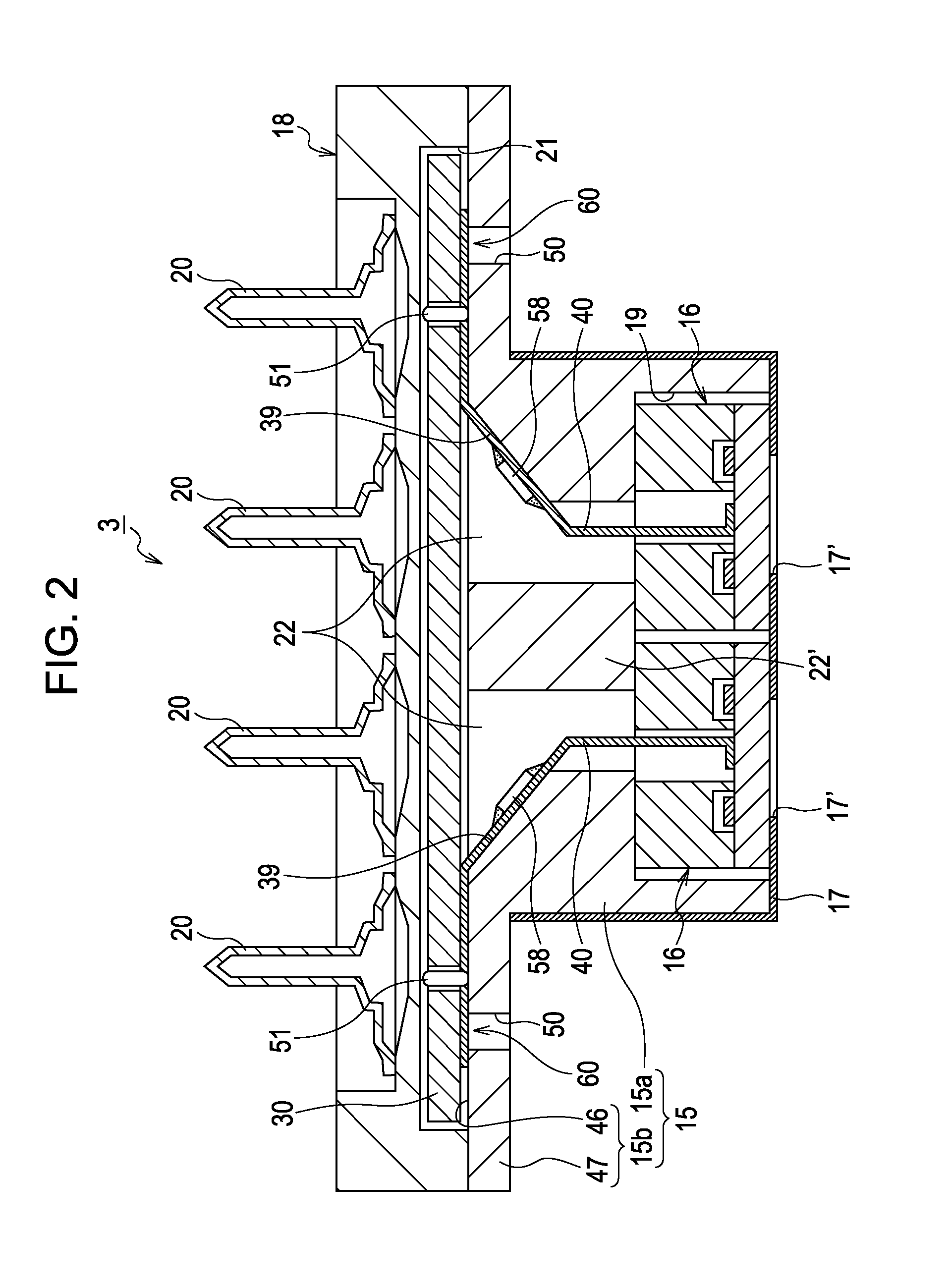
[0027]Referring now to attached drawings, embodiments of the invention will be described below. In the embodiments described below, various definitions are made as preferred embodiments of the invention. However, the scope of the invention is not limited to these modes unless otherwise specified in description given below to the effect of defining the invention. In the description given below, an ink jet printer (a type of liquid ejecting apparatus of the invention) including an ink jet recording head as a type of liquid ejecting head (hereinafter, referred to as a recording head) will be exemplified as the liquid ejecting apparatus of the invention.

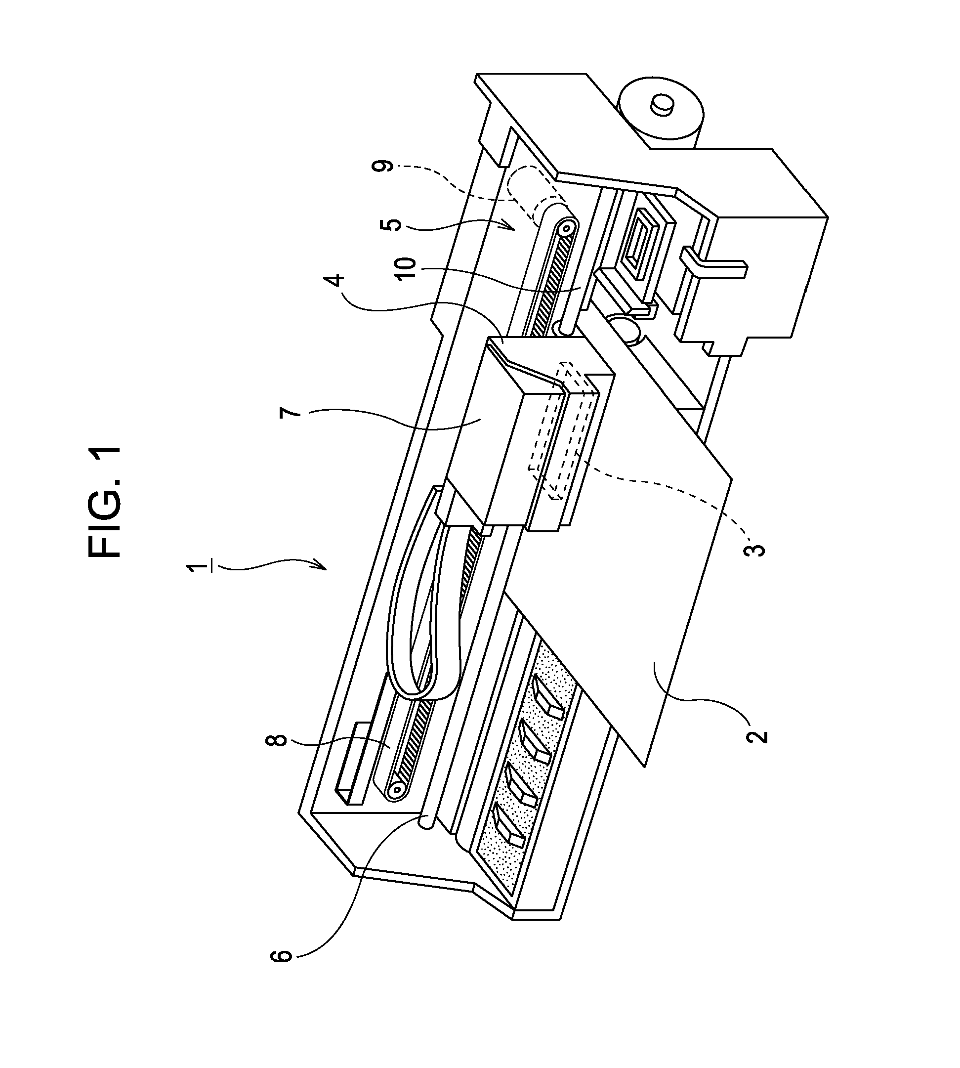
[0028]Referring now to FIG. 1, a configuration of a printer 1 will be described. The printer 1 is an apparatus configured to perform recording of an image or the like by ejecting liquid ink to a surface of a recording medium 2 (a type of an object to be ejected) such as a recording sheet or the like. The printer 1 includes a recording he...


PUM


Abstract

A head unit fixed to a case in a position in which a nozzle forming surface thereof faces a first surface side of a head fixing portion, and a wiring substrate is arranged on a second surface side opposite from the first surface on a portion. A supply flow channel in the case communicate with a common liquid chamber at an end portion of the communicating flow channel in a first direction, and a flexible cable is disposed inside the supply flow channel in the case in the first direction.

Description

[0001]This application claims a priority to Japanese Patent Application No. 2011-246065 filed on Nov. 10, 2011 which is hereby expressly incorporated by reference herein in its entirety.BACKGROUND[0002]1. Technical Field[0003]The present invention relates to a liquid ejecting head such as an ink jet recording head and a liquid ejecting apparatus and, more specifically, to a liquid ejecting head including a holding member provided with a head unit configured to eject liquid from a nozzle, a wiring member configured to be electrically connected to pressure generating units, and a wiring substrate configured to supply drive signals to the pressure generating units through the wiring member, and a liquid ejecting apparatus.[0004]2. Related Art[0005]A liquid ejecting apparatus is an apparatus including a liquid ejecting head, and configured to eject various types of liquid from the liquid ejecting head. Examples of a liquid ejecting apparatus include image recording apparatuses such as i...

Claims


Application Information

Patent Timeline
Patent Type & Authority Applications(United States)
IPC IPC(8): B41J2/14
CPCB41J2/14233B41J2002/14491B41J2002/14362
Inventor ENOMOTO, KATSUMIWATANABE, SHUNSUKEFUKUZAWA, YUMAOGUCHI, SATOSHI
Owner SEIKO EPSON CORP
Why Eureka
Try Eureka