State monitor apparatus

Inactive Publication Date: 2013-05-16
DENSO CORP
View PDF3 Cites 4 Cited by
  • Summary
  • Abstract
  • Description
  • Claims
  • Application Information

AI Technical Summary

Benefits of technology

The patent describes a device that monitors and reduces electricity consumption by detecting and preventing unnecessary light emissions. This device uses a specific restriction process to stop the light emitter from emitting too much near-infrared light and reducing electricity consumption. The technical effect of this invention is to save energy and reduce carbon dioxide emissions by reducing electricity consumption.

Problems solved by technology

The state monitor apparatus may be displaced due to some causes such as vibration during the traveling of the vehicle from the prespecified position.
When the installed position of the state monitor apparatus varies from the prespecified position, in particular, when the installed position of the light emitter is displaced from the prespecified position, a disadvantage may occur as follows.
Alternatively, even when radiating to an area covering the occupant's face, the strength level of the near-infrared lights reaching the face may become too brighter or darker than a predetermined level, possibly capturing an image unsuitable for monitoring the occupant.
Thus, the state monitor apparatus, in particular, an operation of the light emitter is unnecessary for the purpose of a safe travel of the vehicle.
As a result, in a conventional state monitor apparatus, even though it is unnecessary, the near-infrared lights are emitted in a predetermined strength, increasing uselessly the electricity consumption.

Method used


Image

  • State monitor apparatus
  • State monitor apparatus
  • State monitor apparatus

Examples


embodiment

Effect of Embodiment

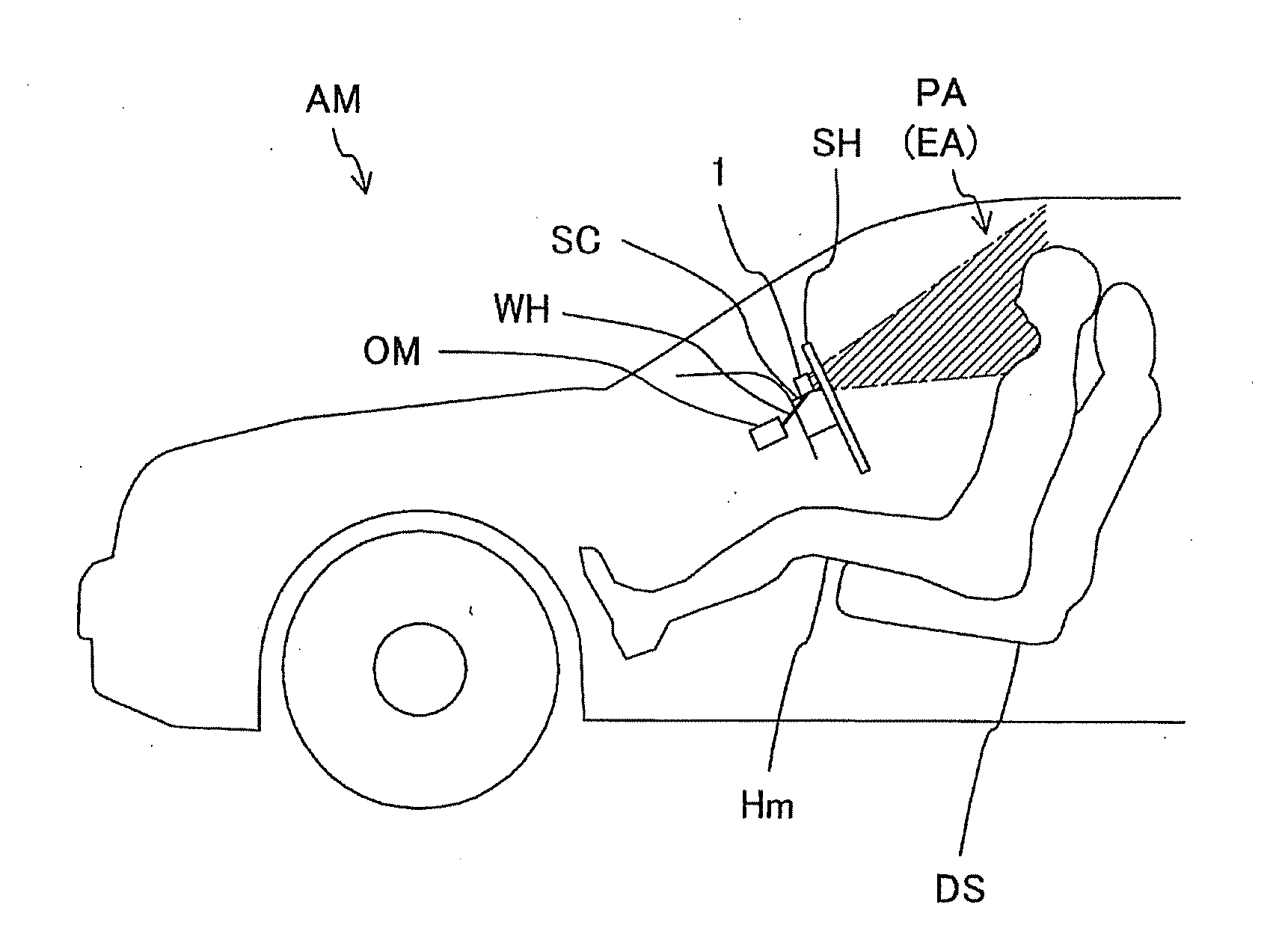
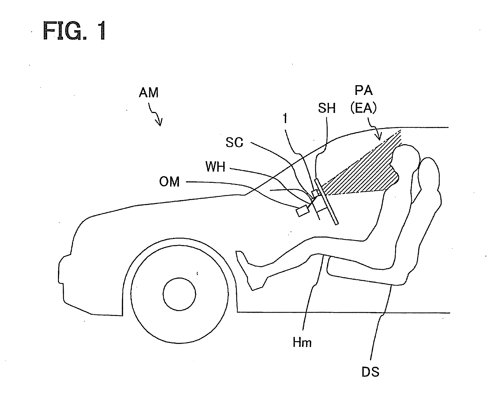
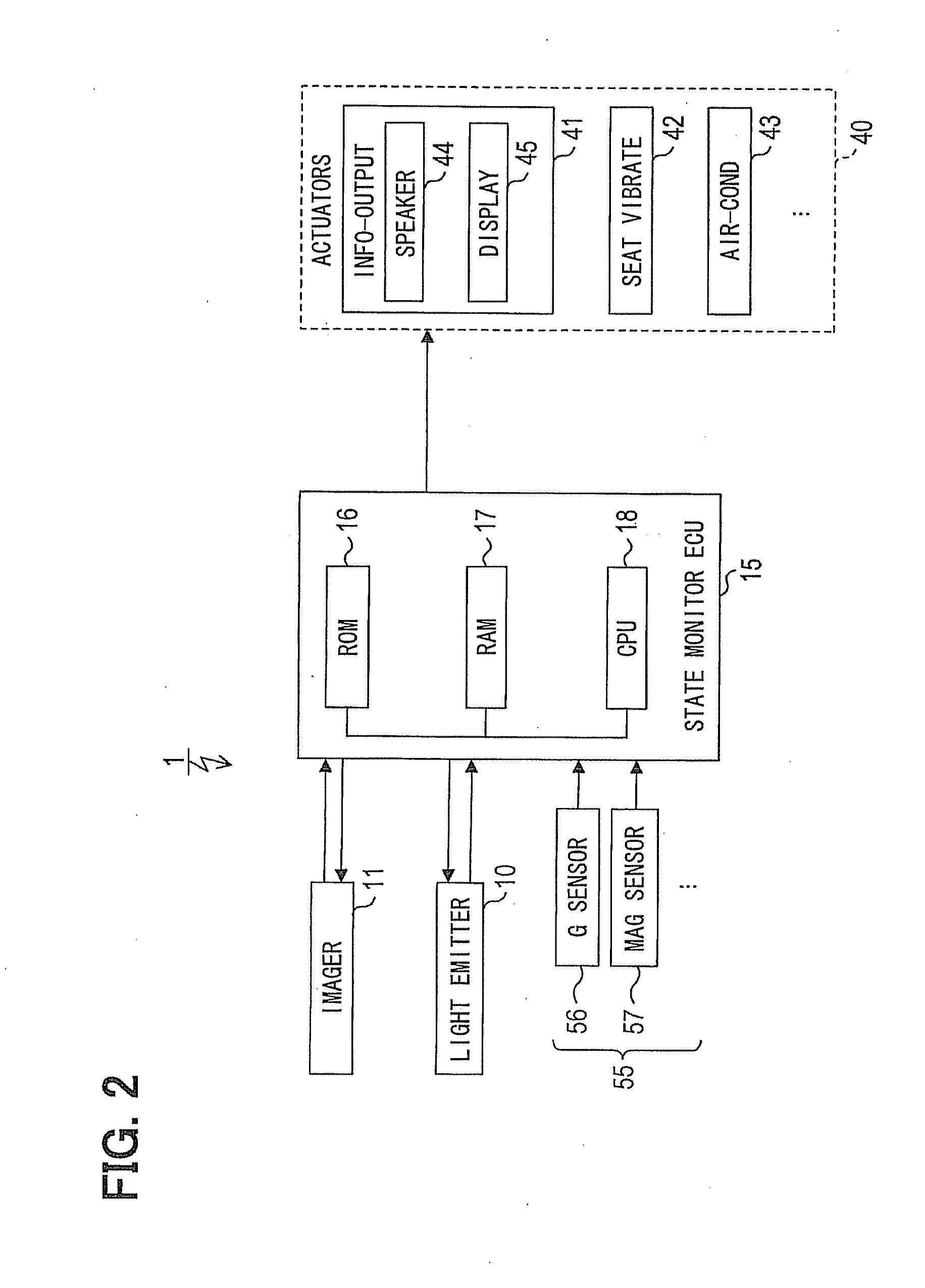
[0076]According to the state monitor apparatus 1, when the stop state takes place, the level of the near-infrared lights emitted by the light emitter 10 may be reduced to be less than the lower limit of the control range of the near-infrared lights. As a result, the stop state taking place precludes the near-infrared lights from radiating with a strength level higher than needed.

[0077]In particular, in the state monitor apparatus 1 of the present embodiment, when the stop state takes place, the emission of the near-infrared lights by the light emitter 10 is prohibited. Therefore, when the stop state takes place, the near-infrared lights having a strong strength more than needed can be more certainly prevented from radiating.

[0078]In addition, when the stop state takes place in the state monitor apparatus 1, a warning is outputted which indicates that the emission of the near-infrared lights is unnecessary, or the installed position of the state monitor apparatus ...


PUM


Abstract

In a state monitor process, it is determined whether a stop state, which requires a stop of a function of a state monitor apparatus, takes place based on detection signals from sensors, namely, it is determined whether an installed position of the state monitor apparatus is displaced from a fixing position or prespecified position. When the installed position of the state monitor apparatus is not displaced from the fixing position, it is determined that the stop state does not take place, permitting a light emitter to irradiate a defined irradiated area with near-infrared lights to capture an image of a driver. When the installed position of the state monitor apparatus is displaced from the fixing position, it is determined that the stop state takes place, executing a restriction process including a reduction process to reduce an emission of the near-infrared lights and a warning output process.

Description

CROSS REFERENCE TO RELATED APPLICATION[0001]The present application is based on Japanese Patent Application No. 2011-246733 filed on Nov. 10, 2011, the disclosure of which is incorporated herein by reference.TECHNICAL FIELD[0002]The present disclosure relates to a state monitor apparatus mounted to a vehicle.BACKGROUND ART[0003][Patent document 1] JP 2008-167806 A[0004]A conventional driver monitoring system or state monitor apparatus monitors an occupant of a vehicle using a camera to achieve a safe travel of the vehicle, as described in Patent document 1.[0005]Such a state monitor apparatus in Patent document 1 has a light emitter to emit near-infrared lights in a predetermined intensity level, an imager to capture an image, and a state monitor section to monitor a state of the occupant based on a result of image-processing of the image captured.[0006]The light emitter is installed at a prespecified position to irradiate a defined irradiated area covering a face of the occupant of...

Claims


Application Information

Patent Timeline
IPC IPC(8): H04N7/18
CPCH04N7/188B60K28/06B60W2540/22B60Y2302/07B60W2420/403G08B21/06
Inventor OMI, TAKUHIRO
Owner DENSO CORP
Why Eureka
Try Eureka