Communication systems with enhanced isolation provision and optimized impedance matching

a technology of impedance matching and isolation provision, applied in the direction of transmission, electrical equipment, etc., can solve the problems of damage to sensitive components, signals in different frequency bands,

Active Publication Date: 2013-05-16
KYOCERA AVX COMPONENTS (SAN DIEGO) INC
View PDF4 Cites 57 Cited by
  • Summary
  • Abstract
  • Description
  • Claims
  • Application Information

AI Technical Summary

Problems solved by technology

In particular, signals in different frequency bands in such a dense RF circuitry tend to interfere with each other, and in some cases even damage sensitive components if the gap between the bands is small.

Method used


Image

  • Communication systems with enhanced isolation provision and optimized impedance matching
  • Communication systems with enhanced isolation provision and optimized impedance matching
  • Communication systems with enhanced isolation provision and optimized impedance matching

Examples


Embodiment Construction

[0016]In view of the isolation considerations for a multi-mode multi-band communication system having multiple paths, this document provides implementations and examples of communication systems configured to provide an enhanced isolation provision. The system may include an antenna comprising multiple feeds coupled to the multiple paths, respectively, to provide physical separation of the multiple paths from each other. The antenna is configured to provide impedance matching for each of the multiple paths. The physical separation of the multiple paths and the impedance matching for each of the multiple paths may provide isolation among the multiple paths, and relax rejection considerations on the filters. Specific implementations and examples are described below with reference to the corresponding figures.

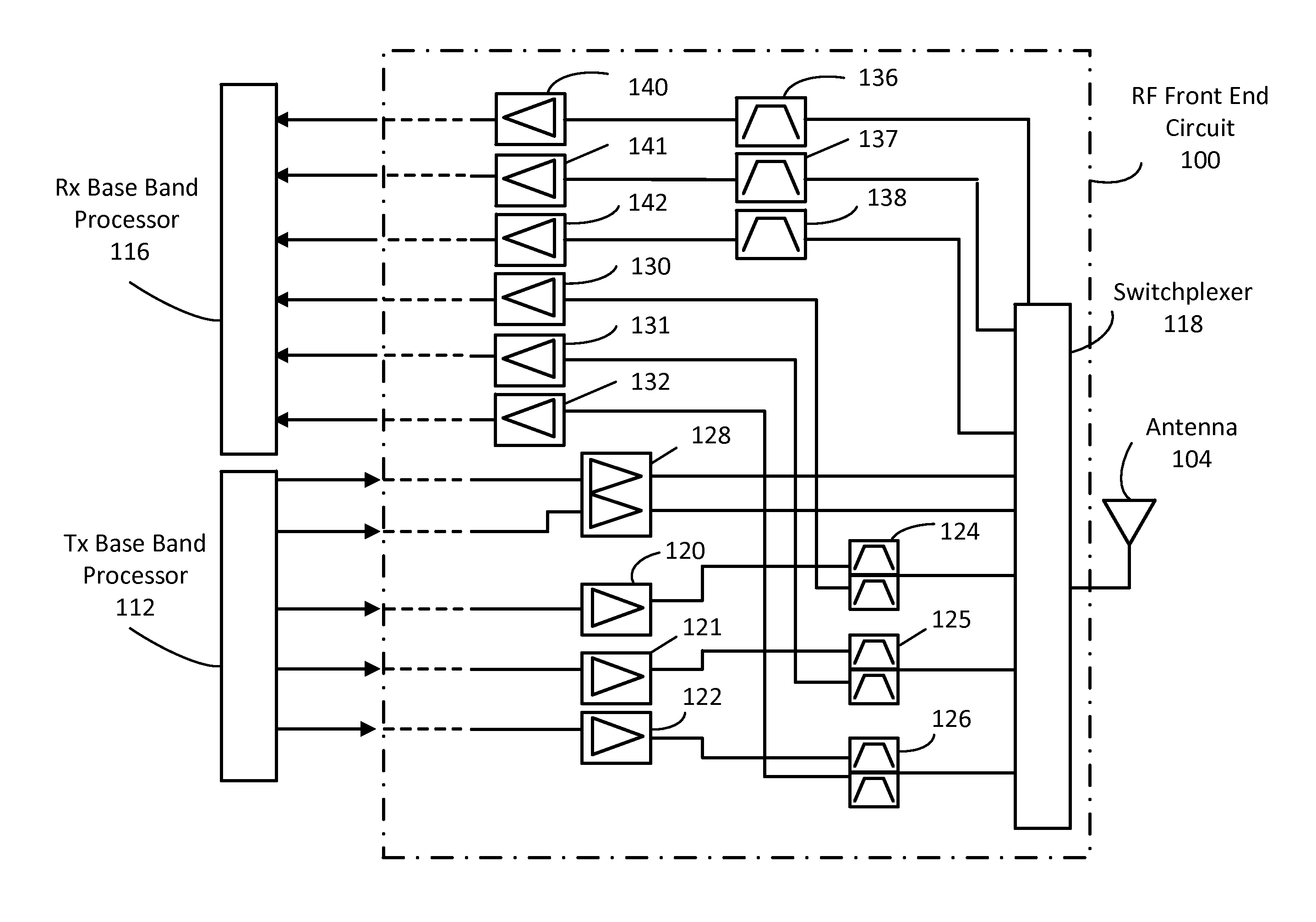
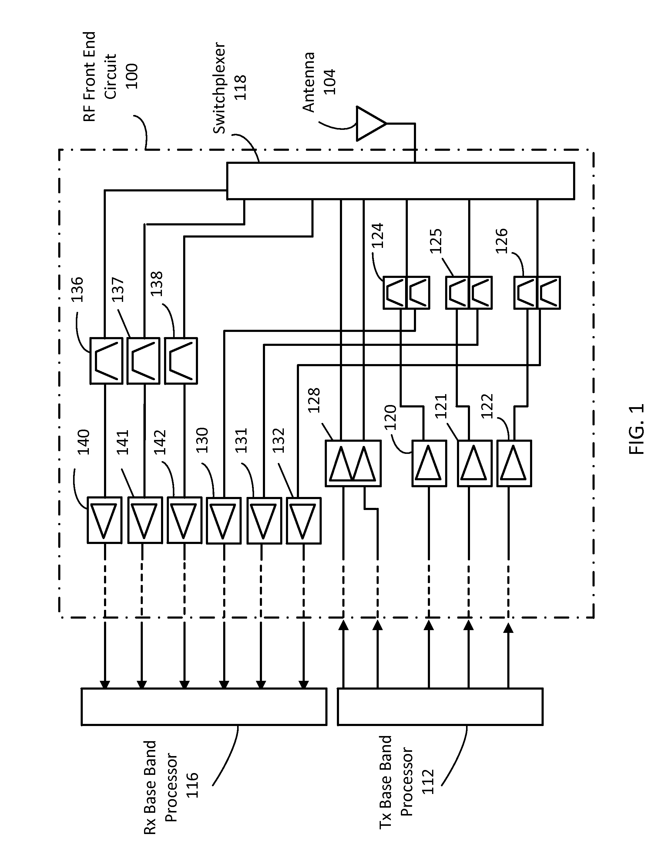
[0017]FIG. 1 illustrates an example of an architecture configured for a conventional communication system including an RF front end circuit 100 coupled to an antenna 104, a Tx bas...


PUM


Abstract

A communication system has multiple paths including one or more Tx paths for processing Tx signals and one or more Rx paths for processing Rx signals, one or more PAs coupled respectively to the one or more Tx paths for amplifying the Tx signals, one or more LNAs coupled respectively to the one or more Rx paths for amplifying the Rx signals, one or more Tx filters coupled respectively to the one or more Tx paths for filtering the Tx signals, one or more Rx filters coupled respectively to the one or more Rx paths for filtering the Rx signals, and an antenna comprising multiple feeds coupled to the multiple paths, respectively, to provide physical separation of the multiple paths from each other. Physical separation among the multiple paths and impedance matching provides isolation among the multiple paths, and relaxes rejection considerations on the filters.

Description

CROSS-REFERENCE TO RELATED APPLICATIONS[0001]This application is a Continuation in Part (CIP) of commonly owned U.S. patent application Ser. No. 13 / 548,211, filed Jul. 13, 2012, titled “MULTI-FEED ANTENNA FOR PATH OPTIMIZATION”;[0002]a Continuation in Part (CIP) of commonly owned U.S. patent application Ser. No. 13 / 557,173, filed on Jul. 24, 2012, titled “MULTI-MODE MULTI-BAND SELF-REALIGNING POWER AMPLIFIER”; which claims benefit of priority to U.S. Provisional Application Ser. No. 61 / 511,114, filed Jul. 24, 2011; and[0003]claims benefit of priority with U.S. Provisional Application Ser. No. 61 / 532,414, filed Sep. 9, 2011;[0004]the contents of each of which are hereby incorporated by reference.BACKGROUND OF THE INVENTION[0005]Frequency bands and modes associated with various protocols are specified per industry standards for cell phone and mobile device applications, WiFi applications, WiMax applications and other wireless communication applications, and the number of specified ban...

Claims


Application Information

Patent Timeline
Patent Type & Authority Applications(United States)
IPC IPC(8): H04B1/44
CPCH04B1/525H04B1/44
Inventor DESCLOS, LAURENTDUPUY, ALEXANDRE
Owner KYOCERA AVX COMPONENTS (SAN DIEGO) INC
Why Eureka
Try Eureka