System and method for manufacturing arthroplasty jigs having improved mating accuracy

a cutting jig and arthroplasty technology, applied in the field of systems and methods for manufacturing customized arthroplasty cutting jigs, can solve the problems of pain, stiffness, decreased mobility, and damage to the bones and joints, and achieve the effects of improving the accuracy of cutting, and improving the quality of cutting

Active Publication Date: 2013-05-16
HOWMEDICA OSTEONICS CORP
View PDF0 Cites 44 Cited by
  • Summary
  • Abstract
  • Description
  • Claims
  • Application Information

AI Technical Summary

Benefits of technology

[0011]Disclosed herein is a method of manufacturing an arthroplasty jig. In one embodiment, the method includes: generating two-dimensional images of at least a portion of a bone forming a joint; generating a first three-dimensional computer model of the at least a portion of the bone from the two-dimensional images; generating a second three-dimensional computer model of the at least a portion of the bone from the two-dimensional images; causing the first and second three-dimensional computer models to have in common a reference position, wherein the reference position includes at least one of a location and an orientation relative to an origin; generating a first type of data with the first three-dimensional computer model; generating a second type of data with the second three-dimensional computer model; employing the reference position to integrate the first and second types of data into an integrated jig data; using the integrated jig data at a manufacturing device to manufacture the arthroplasty jig.
[0014]Disclosed herein are arthroplasty jigs manufactured according to any of the aforementioned methods of manufacture. In some embodiments, the arthroplasty jigs may be indexed to matingly receive arthroplasty target regions of a joint bone. The arthroplasty jigs may also be indexed to orient saw cut slots and drill hole guides such that when the arthroplasty target regions are matingly received by the arthroplasty jig, the saw cuts and drill holes administered to the arthroplasty target region via the saw cut slots and drill hole guides will facilitate arthroplasty implants generally restoring the joint to a pre-degenerated state (i.e., natural alignment state).
[0021]Disclosed herein is a femoral arthroplasty jig for assisting in the performance of a femoral arthroplasty procedure on a femoral arthroplasty target region. In one embodiment the jig includes a first side, a second side generally opposite the first side; and a mating surface in the first side and configured to matingly receive and contact certain surfaces of the femoral arthroplasty target region. The certain surfaces may bed limited to a medial articular condyle surface, a lateral articular condyle surface, and a generally planar area of an anterior side of a femoral shaft. The first side may be configured to be oriented towards the femoral arthroplasty target region surface when the mating surface matingly receives and contacts the certain surfaces.
[0022]Disclosed herein is a tibial arthroplasty jig for assisting in the performance of a tibial arthroplasty procedure on a tibial arthroplasty target region. In one embodiment, the jig includes a first side, a second side generally opposite the first side, and a mating surface. The mating surface may be in the first side and configured to matingly receive and contact certain surfaces of the tibial arthroplasty target region. The certain surfaces may be limited to a medial articular plateau surface, a lateral articular plateau surface, and a generally planar area of an anterior side of a tibial shaft. The first side may be configured to be oriented towards the tibial arthroplasty target region surface when the mating surface matingly receives and contacts the certain surfaces.
[0024]Disclosed herein is a femoral arthroplasty jig for assisting in the performance of a femoral arthroplasty procedure on a femoral arthroplasty target region. In one embodiment, the jig includes a first side, a second side generally opposite the first side, and a mating surface in the first side. The mating surface may be configured to matingly receive and contact a generally planar area of an anterior side of a femoral shaft generally proximal of the patellar facet boarder and generally distal an articularis genu. The first side may be configured to be oriented towards the femoral arthroplasty target region surface when the mating surface matingly receives and contacts the planar area.

Problems solved by technology

Over time and through repeated use, bones and joints can become damaged or worn.
When the cartilage wears down, fluid can accumulate in the joint areas, resulting in pain, stiffness, and decreased mobility.
A one- to two-millimeter translational misalignment, or a one- to two-degree rotational misalignment, may result in imbalanced ligaments, and may thereby significantly affect the outcome of the TKA procedure.
For example, implant misalignment may result in intolerable post-surgery pain, and also may prevent the patient from having full leg extension and stable leg flexion.
This is “eyeballing” or manual manipulation of the bone modes on the computer screen is inefficient and unnecessarily raises the time, manpower and costs associated with producing the customized arthroplasty jigs.

Method used


Image

  • System and method for manufacturing arthroplasty jigs having improved mating accuracy
  • System and method for manufacturing arthroplasty jigs having improved mating accuracy
  • System and method for manufacturing arthroplasty jigs having improved mating accuracy

Examples


Embodiment Construction

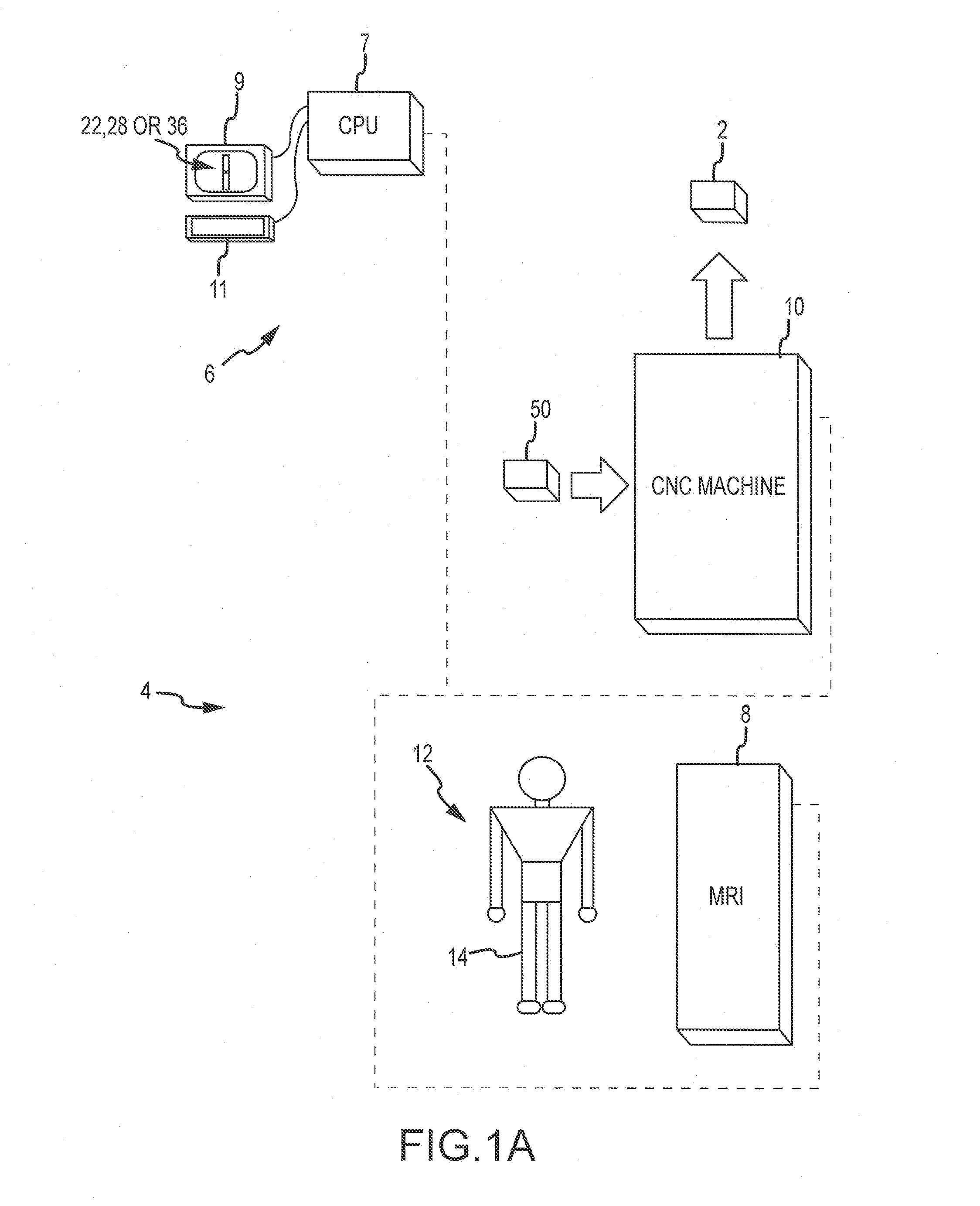
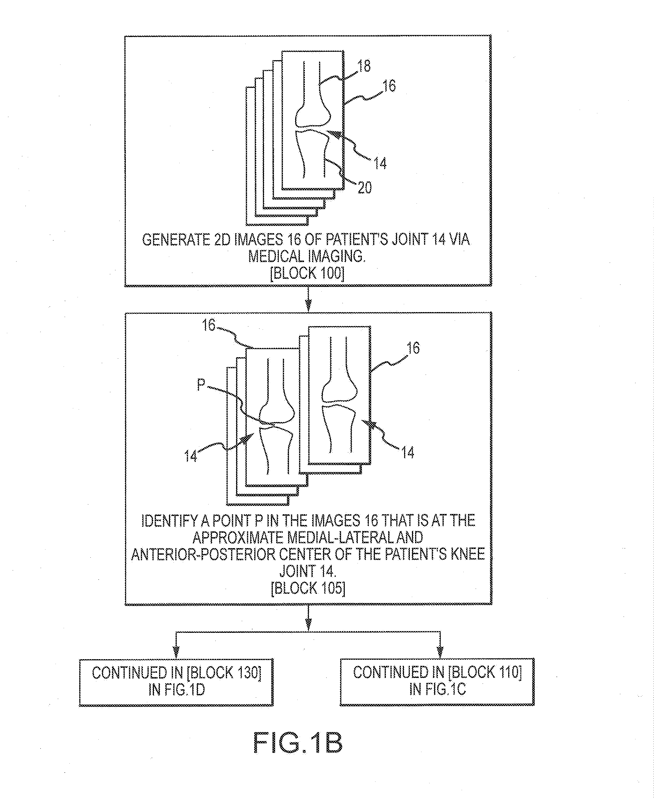
[0117]Disclosed herein are customized arthroplasty jigs 2 and systems 4 for, and methods of, producing such jigs 2. The jigs 2 are customized to fit specific bone surfaces of specific patients. Depending on the embodiment and to a greater or lesser extent, the jigs 2 are automatically planned and generated and may be similar to those disclosed in these three U.S. patent applications: U.S. patent application Ser. No. 11 / 656,323 to Park et al., titled “Arthroplasty Devices and Related Methods” and filed Jan. 19, 2007; U.S. patent application Ser. No. 10 / 146,862 to Park et al., titled “Improved Total Joint Arthroplasty System” and filed May 15, 2002; and U.S. patent Ser. No. 11 / 642,385 to Park et al., titled “Arthroplasty Devices and Related Methods” and filed Dec. 19, 2006. The disclosures of these three U.S. patent applications are incorporated by reference in their entireties into this Detailed Description.

[0118]a. Overview of System and Method for Manufacturing Customized Arthropla...


PUM


Abstract

Disclosed herein is a method of defining a mating surface in a first side of an arthroplasty jig. The mating surface is configured to matingly receive and contact a corresponding patient surface including at least one of a bone surface and a cartilage surface. The first side is oriented towards the patient surface when the mating surface matingly receives and contacts the patient surface. The method may include: a) identifying a contour line associated with the patient surface as represented in a medical image; b) evaluating via an algorithm the adequacy of the contour line for defining a portion of the mating surface associated with the contour line; c) modifying the contour line if the contour line is deemed inadequate; and d) employing the modified contour line to define the portion of the mating surface associated with the contour line.

Description

CROSS-REFERENCE TO RELATED APPLICATIONS[0001]The present application is a divisional application of U.S. application Ser. No. 12 / 505,056, filed Jul. 17, 2009, which application claims the benefit of priority under 35 USC §119(e) to U.S. Patent Application No. 61 / 083,053 entitled “System and Method for Manufacturing Arthroplasty Jigs Having Improved Mating Accuracy,” and filed Jul. 23, 2008. Each application referenced above is hereby incorporated by reference in its entirety as if fully set forth herein.FIELD OF THE INVENTION[0002]The present invention relates to systems and methods for manufacturing customized arthroplasty cutting jigs. More specifically, the present invention relates to automated systems and methods manufacturing such jigs.BACKGROUND OF THE INVENTION[0003]Over time and through repeated use, bones and joints can become damaged or worn. For example, repetitive strain on bones and joints (e.g., through athletic activity), traumatic events, and certain diseases (e.g.,...

Claims


Application Information

Patent Timeline
Patent Type & Authority Applications(United States)
IPC IPC(8): A61B17/16
CPCA61B17/15A61B17/155A61B17/1764A61B2019/508A61B17/1675A61B17/157A61B2034/108A61B17/58A61B34/10
Inventor PARK, ILWHAN
Owner HOWMEDICA OSTEONICS CORP
Why Eureka
Try Eureka