
Tank sloshing energy recovery system

Active Publication Date: 2013-06-06
PARKER INTANGIBLES LLC
View PDF10 Cites 2 Cited by
  • Summary
  • Abstract
  • Description
  • Claims
  • Application Information

AI Technical Summary

Benefits of technology

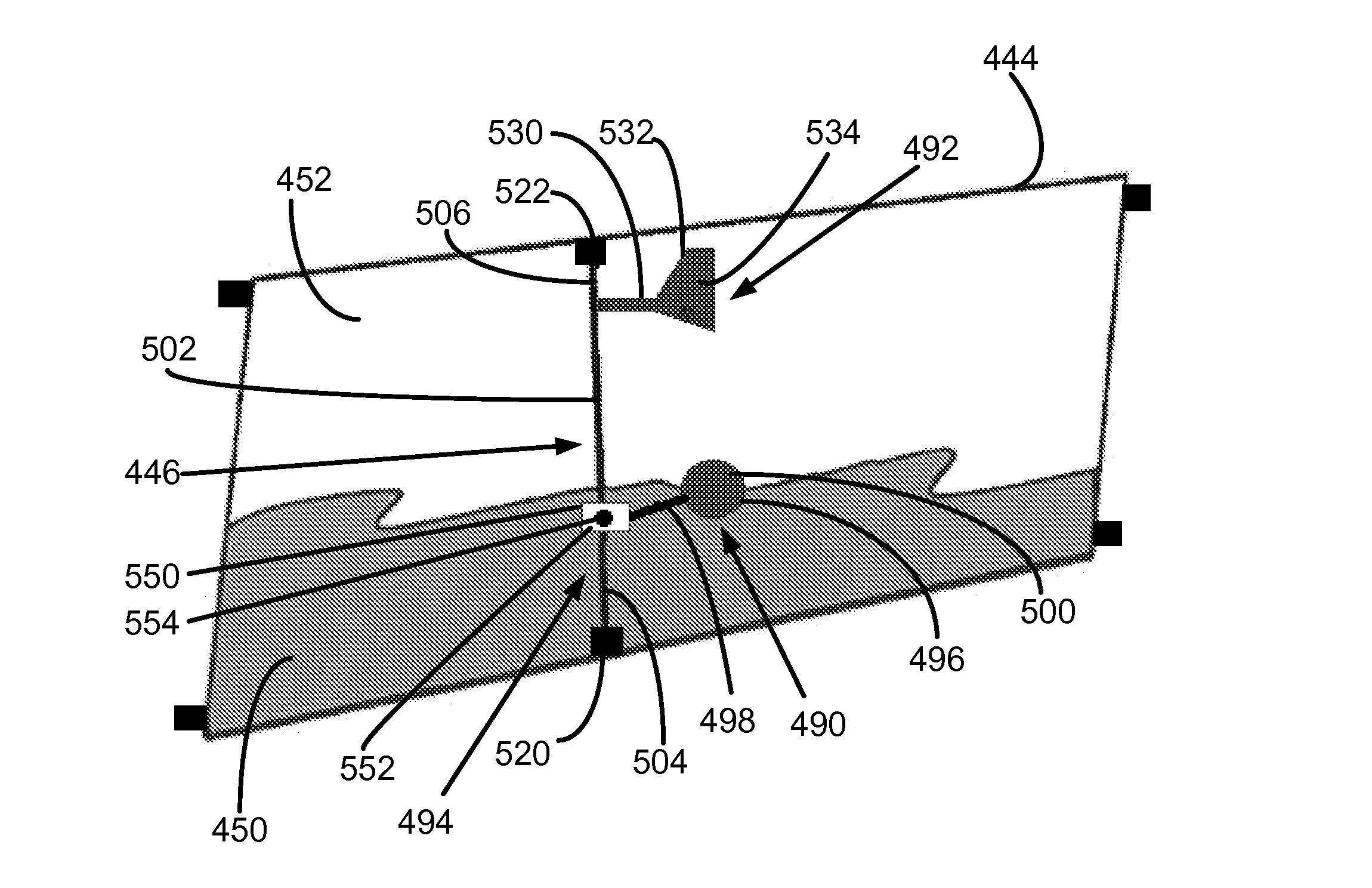
The present invention provides a system for mixing gases in a liquid-filled vessel without using electrical power or transferring motion through the vessel's external wall. The system includes a hydrodynamic actuator that converts the energy of moving liquid into energy for moving the gases in the rich headspace above the liquid. A mixing device is driven by the actuator to effectively mix the gases. This hydrodynamic energy recovery system offers a novel and safe way to mix gases in a liquid-containment vessel.

Problems solved by technology

Injecting nitrogen-enriched or other inerting gas through injection ports of the fuel tank typically only induces limited mixing of gases in the ullage-space.

Method used


Image

  • Tank sloshing energy recovery system
  • Tank sloshing energy recovery system
  • Tank sloshing energy recovery system

Examples


Embodiment Construction

[0027]The principles of the present invention have general application to energy recovery systems, and particular application to the concept of energy extraction from bulk liquid motion at a small scale, such as the energy extraction from the bulk motion of liquid sloshing, flowing, or otherwise moving in a liquid-containment vessel due to motion induced in the liquid. More particularly, the principles of the present invention have application to energy recovery systems of liquid-containment vessels of vehicles, such as aircraft fuel tanks, and thus will be described below chiefly in this context. It will of course be appreciated, and also understood, that the principles of the invention may be useful in other applications including, in particular, in other vehicles having liquid-containment vessels, such as watercraft, spacecraft, and land-vehicles.

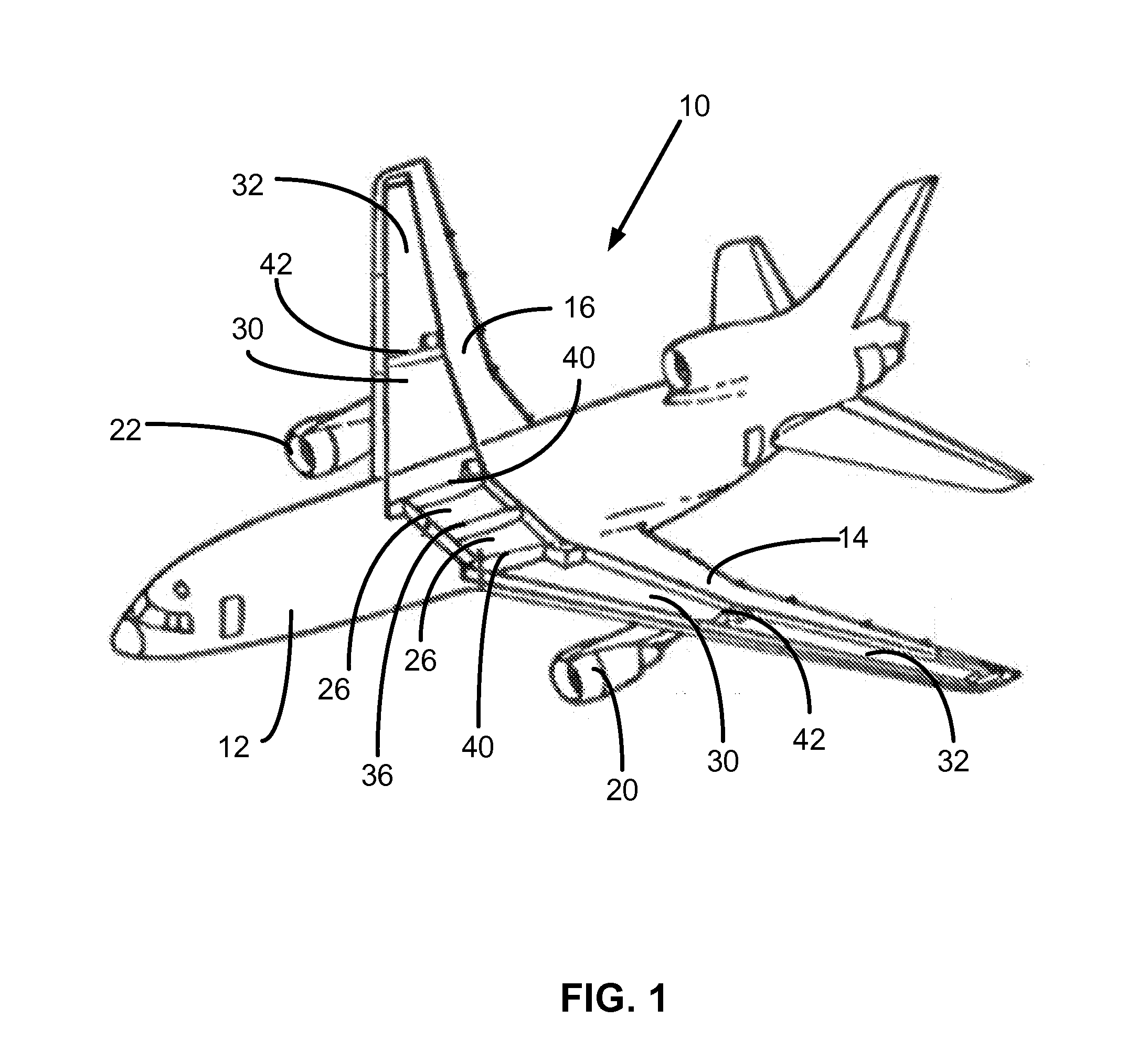
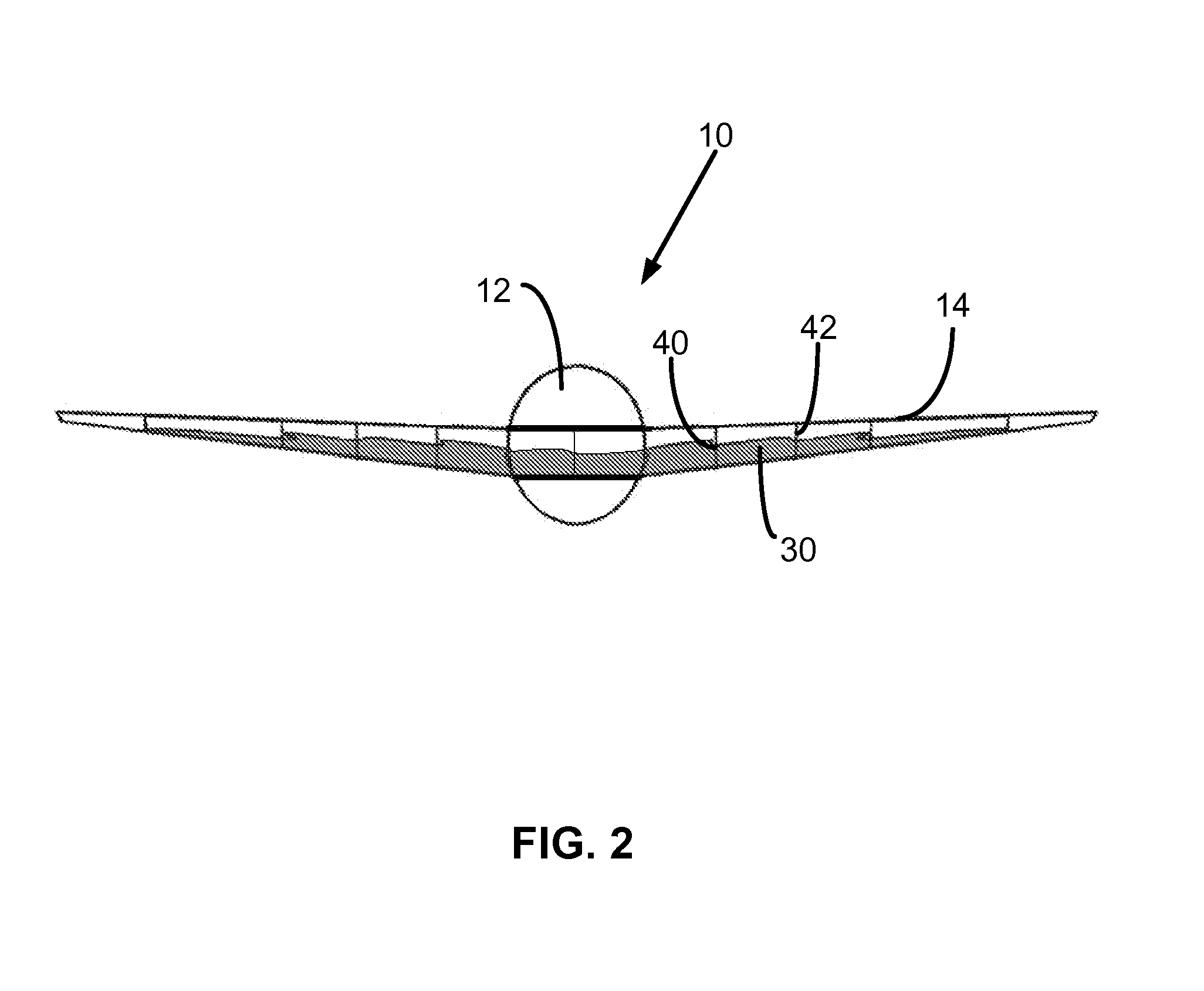
[0028]Referring now in detail to the drawings and initially to FIGS. 1 and 2, a vehicle, specifically an aircraft 10, includes a body o...


PUM


Abstract

A hydrodynamic energy recovery system for effecting mixing of gases within a headspace of a liquid-containment vessel containing a liquid enables mixing of the gases by converting energy of moving or sloshing liquid in a liquid-filled lower portion of the vessel into energy for moving the gases. The system includes (1) a hydro-driven actuator that is movably driven in response to the movement of the liquid in the vessel, (2) a mixing device driven by the actuator such that motion of the mixing device effects mixing of the gases contained in the headspace above the liquid, and (3) a motion converter for converting motion of the actuator into motion for driving the mixing device. The mixing device can be driven without the need to run electrical power within the vessel and without the transfer of motion through an external wall of the vessel.

Description

RELATED APPLICATIONS[0001]This application claims the benefit of U.S. Provisional Application No. 61 / 566,716 filed Dec. 5, 2011, which is hereby incorporated herein by reference.FIELD OF INVENTION[0002]The present invention relates generally to energy recovery systems, and more particularly to an apparatus and method characterized by a hydrodynamic energy recovery system for effecting movement of gases in the headspace of a liquid-containment vessel, such as an aircraft fuel tank.BACKGROUND[0003]A liquid-containment vessel of a vehicle, such as a fuel tank of an aircraft, watercraft, or land vehicle, typically includes a liquid-filled lower portion containing liquid, such as fuel or other fluid, and a gas-filled headspace, such as an ullage-space, above the liquid-filled lower portion. In the context of a fuel tank, the ullage-space is typically filled with fuel vapors in addition to other gases, such as nitrogen-enriched air, to reduce the risk of an explosion via fuel vapor igniti...

Claims


Application Information

Patent Timeline
IPC IPC(8): F01D5/02
CPCF01D5/02B64D37/06Y02B10/50F03B13/00F05B2220/602B64D37/32
Inventor MEHRING, CARSTEN
Owner PARKER INTANGIBLES LLC
Learn More