Electrostatic atomizing device

a technology of atomizing device and electric charge, which is applied in the direction of electrostatic heating/cooling, electrostatic spraying apparatus, burner, etc., can solve the problem of instable generation of charged fine water particles

Inactive Publication Date: 2013-06-13
PANASONIC CORP
View PDF2 Cites 9 Cited by
  • Summary
  • Abstract
  • Description
  • Claims
  • Application Information

AI Technical Summary

Benefits of technology

[0015]The present invention provides an electrostatic atomizing device that generates charged fine water particles in a further preferable manner.

Problems solved by technology

This may lead to instable generation of charged fine water particles.

Method used


Image

  • Electrostatic atomizing device
  • Electrostatic atomizing device
  • Electrostatic atomizing device

Examples


Embodiment Construction

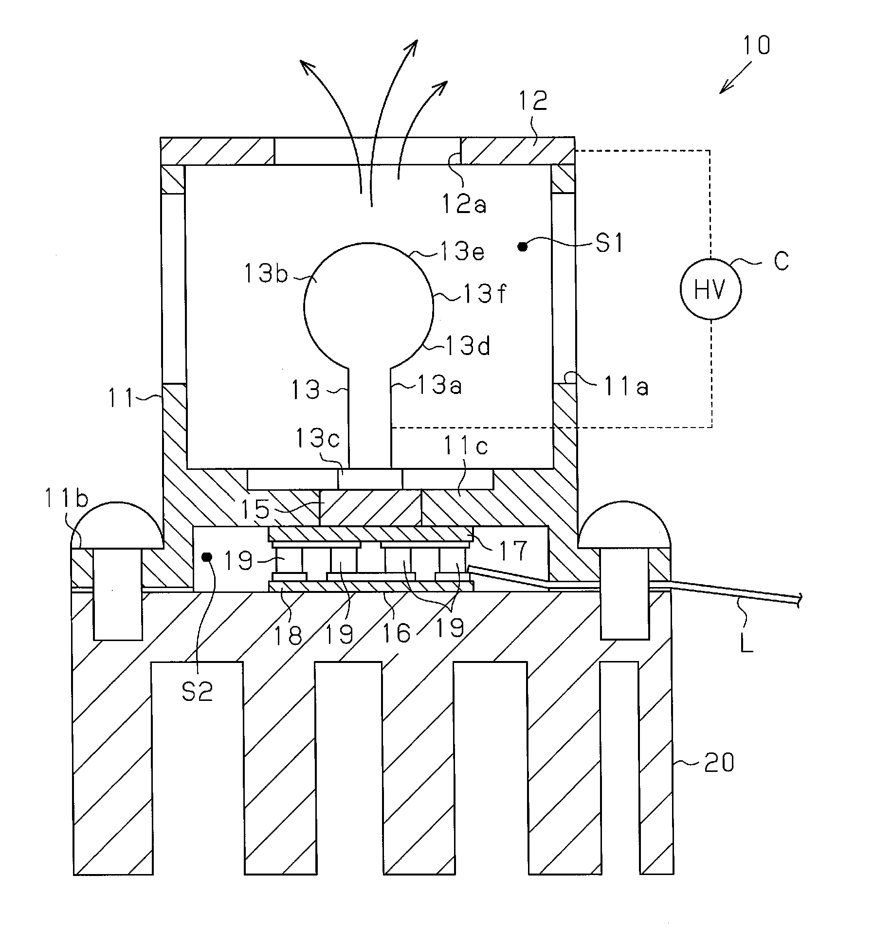
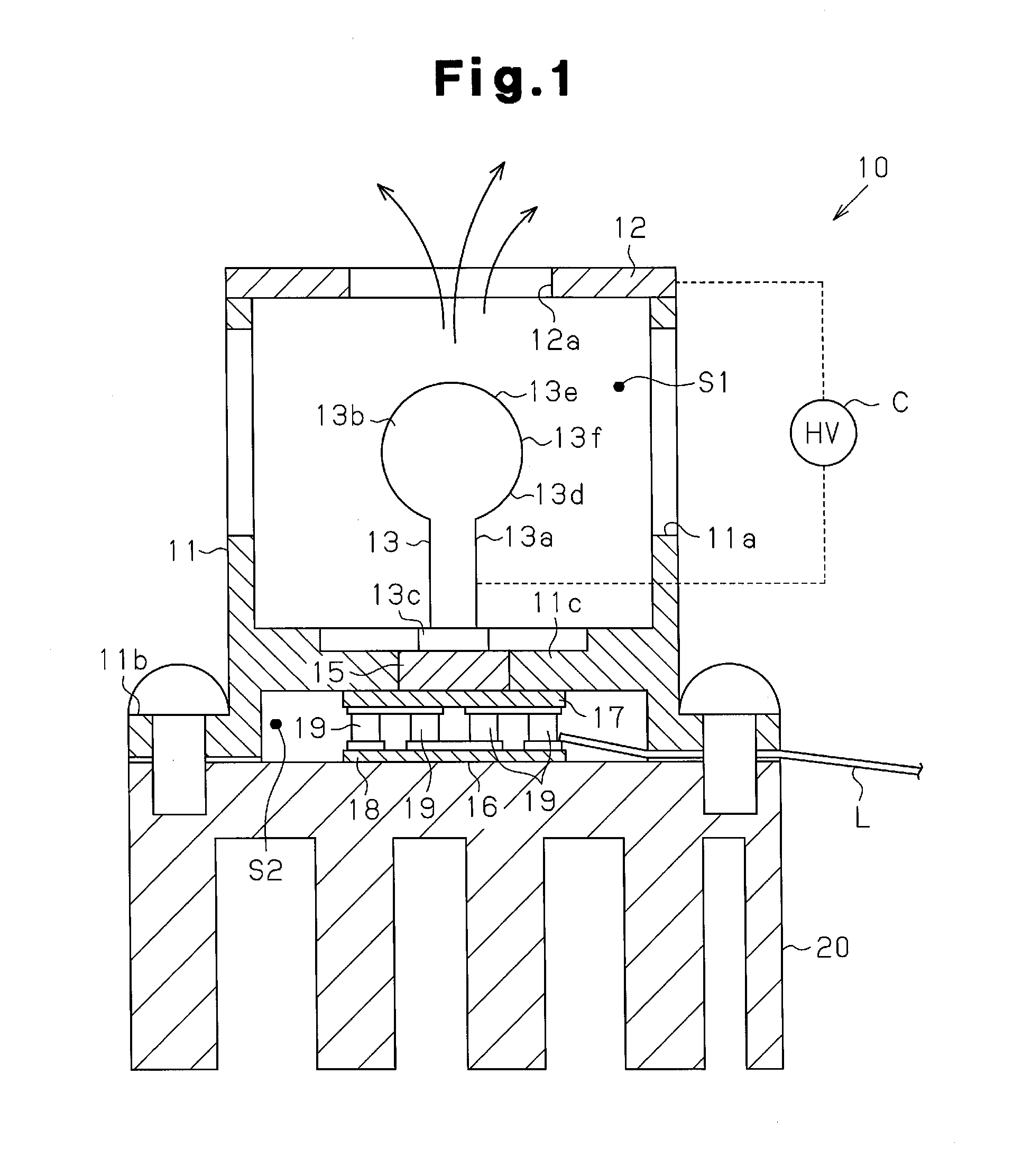
[0020]An electrostatic atomizing device according to one embodiment of the present invention will now be described with reference to the drawings.

[0021]As illustrated in FIG. 1, an electrostatic atomizing device 10 of the present invention includes a support frame 11 formed by an insulative resin material, such as PBT resin, polycarbonate resin, or PPS resin. The support frame 11 includes, for example, a hollow portion 11a and an annular fastening flange 11b, which are formed integrally. The hollow portion 11a is generally cylindrical, and the fastening flange 11b extends outward from the basal portion (bottom portion as viewed in FIG. 1) of the hollow portion 11a. The hollow portion 11a includes an inner surface formed integrally with a partition wall 11c that divides the internal space of the support frame 11 into an atomizing void S1 and a sealed void S2. The hollow portion 11a has a distal surface (top surface as viewed in FIG. 1) on which a ring-shaped opposing electrode 12 is ...


PUM


Abstract

The atomizing electrode of the electrostatic atomizing device has a discharging part and a base. A portion of the atomizing electrode between the discharging part and the base is a large diameter part with a diameter larger than the base. The large diameter part separates condensed water retained near the base from condensed water retained on the discharging part.

Description

TECHNICAL FIELD[0001]The present invention relates to an electrostatic atomizing device that generates charged fine water particles.BACKGROUND ART[0002]Patent document 1 describes an example of an electrostatic atomizing device that cools an atomizing electrode (discharge electrode in patent document 1) to generate condensed water on the electrode. The condensed water held on the atomizing electrode is then atomized by the atomizing electrode to generate charged fine water particles, which are mildly acidic and include electric charges. The charged fine water particles function to moisturize skin and hair and function to deodorize air and articles. Thus, many effects may be obtained by using the electrostatic atomizing device in various products.[0003]In the electrostatic atomizing device of patent document 1, a cooling unit such as a Peltier module is used to cool the atomizing electrode and generate condensed water on the surface of the atomizing electrode.PRIOR ART DOCUMENTSPaten...

Claims


Application Information

Patent Timeline
Patent Type & Authority Applications(United States)
IPC IPC(8): B05B5/00
CPCB05B5/057B05B5/001B05B5/0255
Inventor IMAI, TAKESHIKOBAYASHI, KENTARONAKADA, TAKAYUKIOMORI, TAKAFUMIYAMADA, YUSUKE
Owner PANASONIC CORP
Why Eureka
Try Eureka