
Printing system, raster ouput scanner, and method with electronic banding compensation using facet-dependent smile correction

a printing system and scanner technology, applied in printing, inking apparatus, electrical equipment, etc., can solve problems such as inability to accept reprographic printing systems, periodic density variations in process directions, and density variations in marking materials fused to final print media, and achieve the effect of facilitating correction of position-dependent variation in fast scan direction

Inactive Publication Date: 2013-06-13
XEROX CORP
View PDF8 Cites 2 Cited by
  • Summary
  • Abstract
  • Description
  • Claims
  • Application Information

AI Technical Summary

Benefits of technology

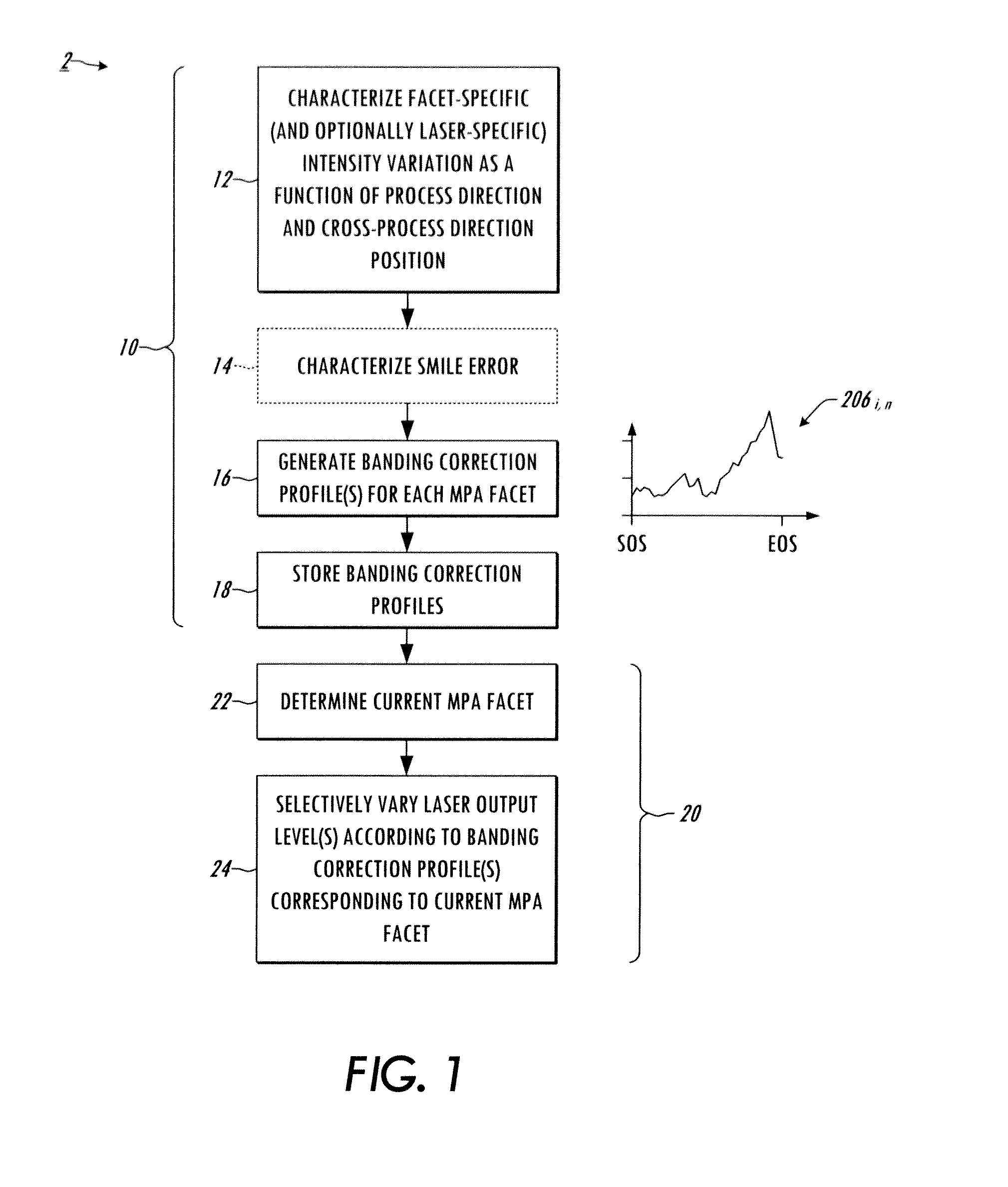
The present patent relates to electronic banding compensation in reprographic systems such as printers, multifunction devices, etc. The disclosed systems and techniques provide the ability to correct the cross-process dependence of the process direction variations attributable to a raster output scanner. The patent provides an actuator, in certain embodiments a ROS light output profile, that varies in the fast scan direction to correct periodic density variations due to ROS polygon errors, including facet dependent variations. The patent also provides a ROS controller that causes the driver to selectively vary the output level of the modulated light output(s) during scanning by a given reflective facet of the rotating polygon to mitigate banding using a given one of a plurality of banding correction profiles that corresponds to the given reflective facet. This approach advantageously facilitates correction of fast scan direction position-dependent variation in sources of banding error, such as polygon facets, etc.

Problems solved by technology

Final image quality is affected by various sources of noise and errors in a reprographic system, leading to density variations in the marking material fused to the final print medium.
Certain sources of reprographic system noise and errors caused periodic density variations in the process direction, which are sometimes referred to as “banding” errors.
Other sources of banding errors include gears, pinions, and rollers in charging and development modules; jitter and wobble in imaging modules, as well as photoreceptors and associated drive trains.
If not addressed, such periodic process direction density variations can render a reprographic printing system unacceptable, particularly where the banding errors are visually perceptible.
There are many various errors that produce banding at the 1× (and multiples) of the revolution frequency of the MPA (motor polygon assembly) in reprographic systems using a raster output scanner.
In practice, it is difficult to completely eliminate the error sources that contribute to MPA harmonic banding, or even to reduce them enough to avoid perceptible periodic density variations.
However, conventional banding compensation approaches do not address cross-process (fast scan) direction density variation in banding, and instead average test prints in the cross-process direction to get a one-dimensional banding profile which is then used to derive the banding compensation independent of cross-process banding density variation information).

Method used


Image

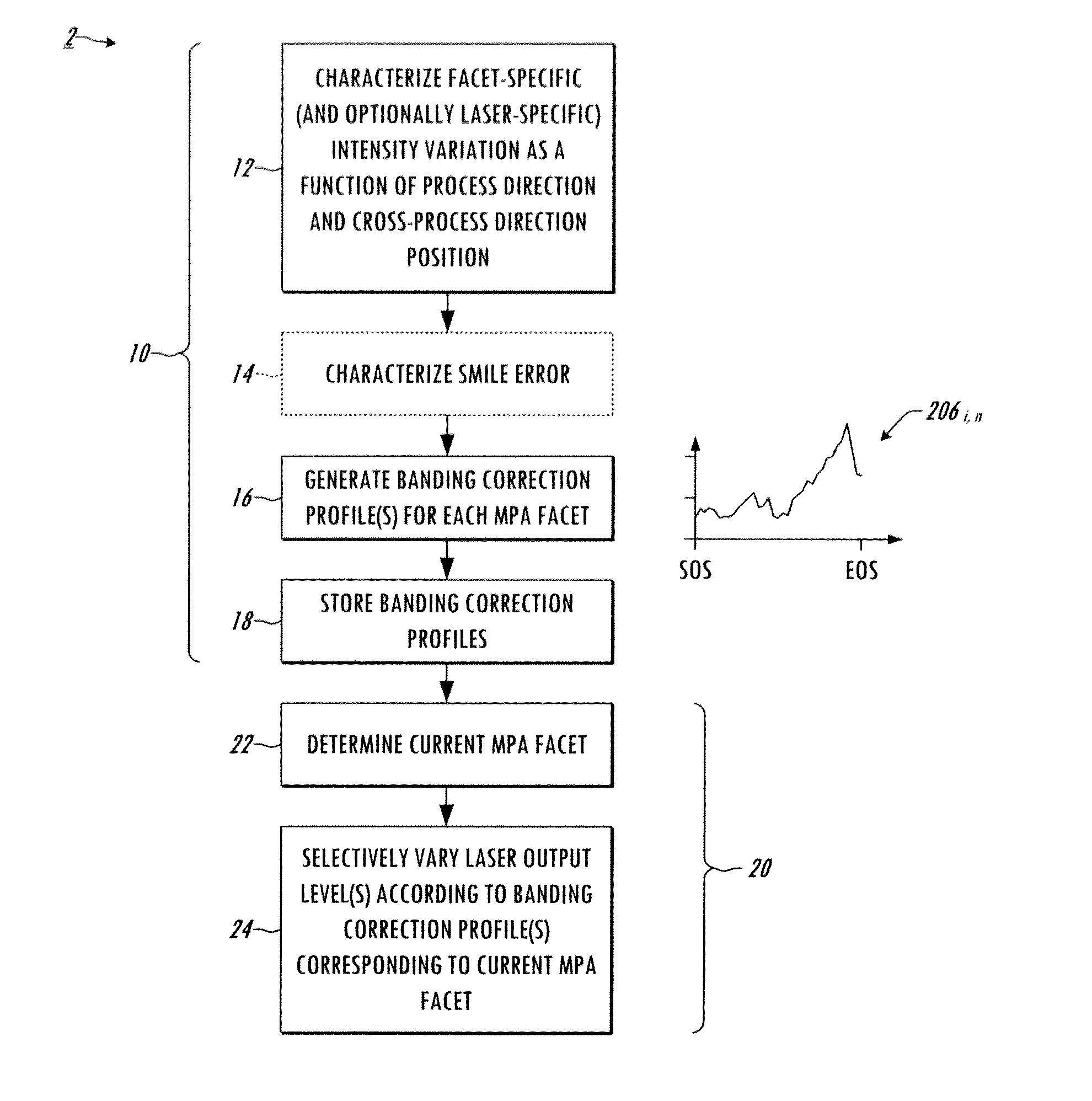
  • Printing system, raster ouput scanner, and method with electronic banding compensation using facet-dependent smile correction
  • Printing system, raster ouput scanner, and method with electronic banding compensation using facet-dependent smile correction
  • Printing system, raster ouput scanner, and method with electronic banding compensation using facet-dependent smile correction

Examples


Embodiment Construction

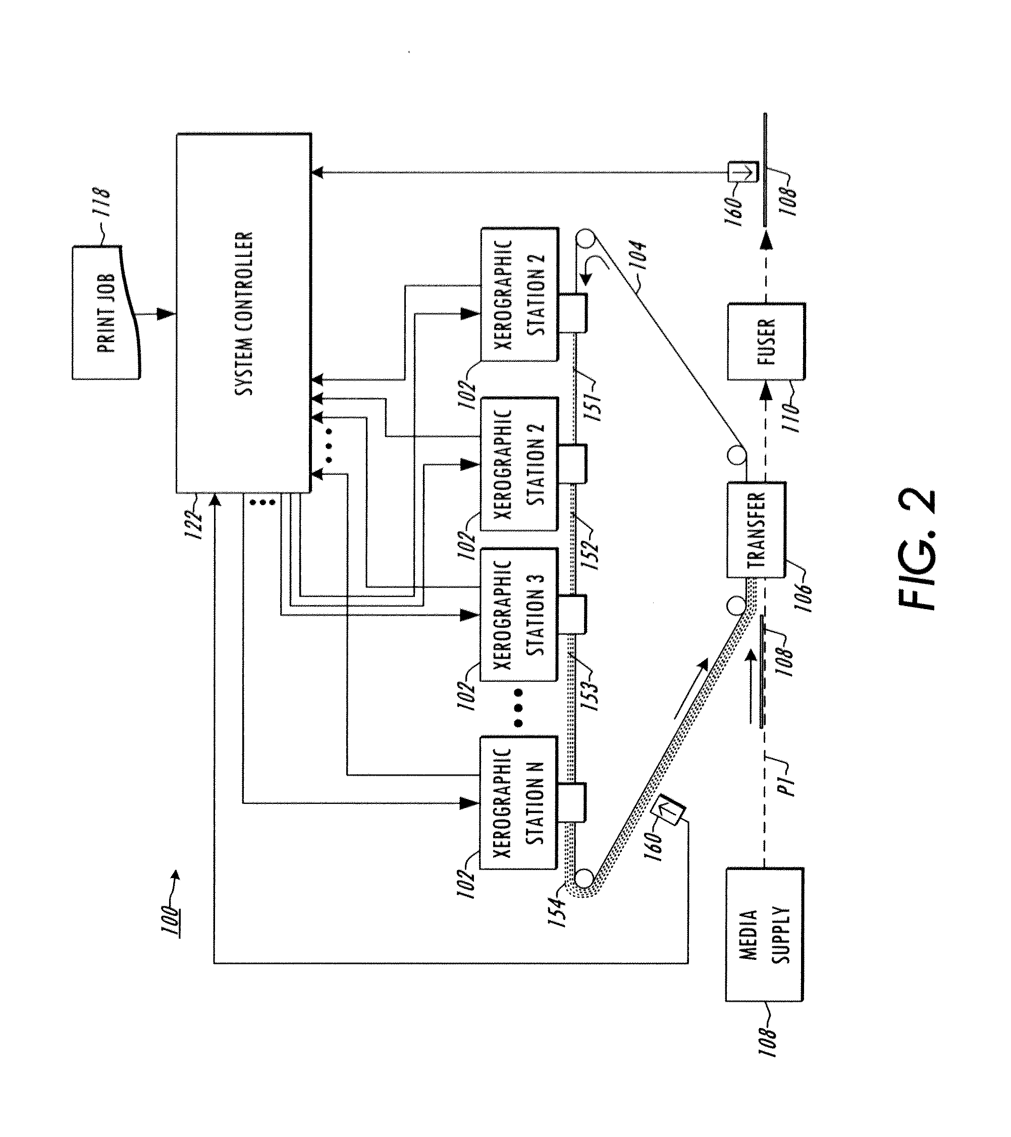
[0014]Several embodiments or implementations of the different aspects of the present disclosure are hereinafter described in conjunction with the drawings, wherein like reference numerals are used to refer to like elements throughout, and wherein the various features, structures, and graphical renderings are not necessarily drawn to scale. The disclosure relates to banding compensation in printing systems employing a single or multi-beam ROS using compensation profile data particularized to individual facets of a multi-facet motor polygon assembly (MPA). The inventors have appreciated that MPA harmonic banding in a printing system often varies in amplitude and phase in the cross-process (fast scan) direction, and that conventional banding compensation techniques failed to address this fast scan direction variation. Further, the inventors have found that conventional fast scan direction compensation, known as smile correction, is incapable of addressing the cross-process direction ba...


PUM


Abstract

Raster Output Scanners and printing systems are presented along with methods for mitigating banding in printing systems, in which electronic banding compensation is employed using cross-process direction light source intensity banding correction profiles tailored to corresponding reflective facets of a rotating polygon.

Description

BACKGROUND[0001]The present exemplary embodiments relate to printing systems with raster output scanner (ROS) apparatus and to techniques for mitigating banding errors. Reprographic printing systems are used to create marked images on paper or other remarkable media, and improving the quality of the produced images is a continuing goal. Final image quality is affected by various sources of noise and errors in a reprographic system, leading to density variations in the marking material fused to the final print medium. In the reprographic process, a photoreceptor travels along a process direction, and images and text are formed as individual scan lines or groups of scan lines (sometimes referred to as a swath) in a raster scanning process in a cross-process direction, where the process direction motion is much slower than the raster scanning in the cross-process direction. Accordingly, the cross-process scanning direction is sometimes referred to as a “fast scan” direction, and the pr...

Claims


Application Information

Patent Timeline
IPC IPC(8): H04N1/04
CPCH04N1/1135H04N1/40025H04N1/12
Inventor HERLOSKI, ROBERTLESTRANGE, JACKCLARK, TIMOTHYGENTNER, JESSSMITH, JR., EDWARD W.MIZES, HOWARDLOCE, ROBERT P.XU, BEILEISHEFLIN, JOSEPH C.
Owner XEROX CORP
Learn More