Method and device for controlling a light emission from a headlight of a vehicle

a technology for headlights and headlights, which is applied in the direction of lighting support devices, transportation and packaging, lighting and heating devices, etc., can solve the problems of not blinding any other, and achieve the effect of reducing the risk of accidents, ensuring safety, and ensuring safety

Inactive Publication Date: 2013-06-13
ROBERT BOSCH GMBH
View PDF4 Cites 18 Cited by
  • Summary
  • Abstract
  • Description
  • Claims
  • Application Information

AI Technical Summary

Benefits of technology

[0007]An advantage of the present invention is that it is possible to set the safety distance in the lighting in such a way that an advantageous balance may be achieved between glare prevention and optimal visual range. Traffic safety may thus be increased, since blinding of a driver of the other vehicle is avoided, and road illumination may be improved. Since the envelope area takes into account the course of the road as well as the position of the other vehicle in the course of the road, a foresighted setting of the safety distance, adapted to the instantaneous course of the road and therefore precise and reliable, is possible. According to one specific embodiment, the envelope area or an envelope curve defining the envelope area is able to be calculated exclusively from camera data that may include object data and lane information. According to an alternative specific embodiment, data of the navigation device may be used in addition to the camera data.
[0008]The present invention provides a method for controlling a light emission from at least one headlight of a vehicle, the method having the following steps:
[0009]Combining lane information with regard to a course of a road and position information regarding at least one other vehicle located in the course of the road, in order to ascertain an envelope area not to be illuminated around the at least one other vehicle; and
[0010]Setting a safety distance between light able to be emitted by the at least one headlight of the vehicle, and the at least one other vehicle based on the envelope area, in order to control the light emission.
[0011]The vehicle may be a motor vehicle, especially a road-bound motor vehicle, e.g., a passenger car or a truck, or a two-wheeler such as a motorcycle. The at least one headlight may be a front headlight of the vehicle, for example. The light emission from the at least one headlight may be alterable in steps. For the control, the light emission from the at least one headlight may be altered in terms of an illumination angle, a light distribution pattern, a brightness, a quantity of light, a level of illumination, a headlight range, a light / dark cutoff and / or the like. Suitable values for the illumination angle, light distribution pattern, brightness, quantity of light, level of illumination, headlight range, light / dark cutoff and / or the like may be selected which make it possible to set the safety distance in such a way that the envelope area around the at least one other vehicle is excepted from the light of the at least one headlight. In this context, the envelope area may surround the at least one other vehicle or may have a surrounding area adjoining the at least one other vehicle. In this connection, the envelope area may represent a safety area which should be excepted from illumination by the at least one headlight. The vehicle may be on the road and may be following the course of the road. If a cyclist is in a bicycle lane next to the road, the cyclist should also not be blinded. In the same way, other vehicles which are driving on a bridge over the road should be considered. That is, the roads in the surround field or field of view of the vehicle or of the course of the road may also be considered, not just the road on which the vehicle is located. The course of the road may thus also include roads forking off from the road. Generally expressed, the course of the road may include an area able to be illuminated by the headlight.
[0012]In this context, in the step of combining, the envelope area may additionally be ascertained from an alignment of the at least one other vehicle relative to the host vehicle. A step of estimating the alignment based on the lane information and the position information may also be provided. The alignment may involve a relationship between a longitudinal axis of the at least one other vehicle, for example, and a longitudinal axis of the host vehicle. The more the alignment of the at least one other vehicle differs from an alignment of the vehicle, the larger at least one dimension of the envelope area can be ascertained. In an estimation or other determination of the alignment, a most probable alignment may be determined or several probable alignments may be determined, through which an average value of the several probable alignments may then be formed. The formation of a weighted sum of the possible alignments as a function of their probabilities is advantageous when ascertaining the most probable alignment. Such a consideration of the alignment of the at least one other vehicle offers the advantage that the envelope area, and therefore also the safety distance, may be adjusted more correctly to a probable orientation of the at least one other vehicle. Thus, illumination of the road as well as prevention of blinding may be improved.

Problems solved by technology

The difficulty lies, inter alia, in not blinding any other vehicle.

Method used


Image

  • Method and device for controlling a light emission from a headlight of a vehicle
  • Method and device for controlling a light emission from a headlight of a vehicle
  • Method and device for controlling a light emission from a headlight of a vehicle

Examples


Embodiment Construction

[0046]In the following description of preferred exemplary embodiments of the present invention, the same or similar reference numerals are used for the similarly functioning elements shown in the various figures, a repeated description of these elements being omitted.

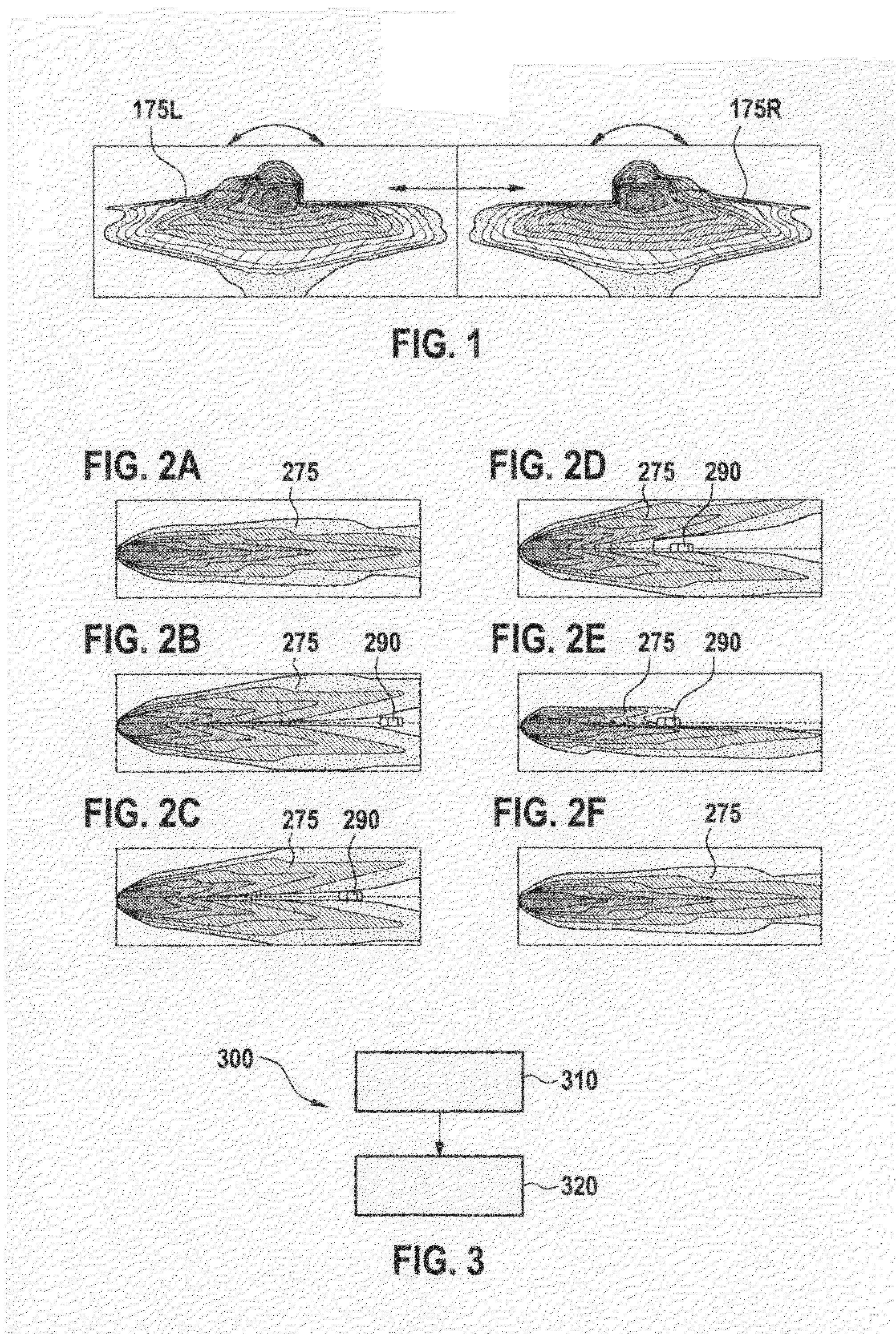
[0047]FIG. 1 shows a schematic representation of emission characteristics of a pair of vehicle headlights. In particular, FIG. 1 shows one possible realization of a glare-free high beam. Shown are a first emission characteristic 175L or first light distribution pattern and a second emission characteristic 175R or second light distribution pattern. First emission characteristic 175L may be assigned to a first headlight of a vehicle, e.g., a left headlight. Second emission characteristic 175R may be assigned to a second headlight of the vehicle, e.g., a right headlight. Arrows in FIG. 1 indicate areas in which emission characteristics 175L and 175R are modified in such a way that the areas indicated by the arrows are exce...


PUM


Abstract

A method for controlling a light emission from at least one headlight of a vehicle combines lane information with respect to a course of a road and position information with regard to at least one other vehicle located in the course of the road, in order to ascertain an envelope area not to be illuminated around the at least one other vehicle. The method also includes setting, based on the envelope area, a safety distance between (i) light able to be emitted by the at least one headlight of the vehicle, and (ii) the at least one other vehicle, in order to control the light emission.

Description

BACKGROUND OF THE INVENTION[0001]1. Field of the Invention[0002]The present invention relates to a method and a device for controlling a light emission from at least one headlight of a vehicle, as well as a corresponding computer-program product.[0003]2. Description of the Related Art[0004]Glare-free high beam, also known as continuous headlight control, CHC, pursues the idea of illuminating the surrounding field in front of a vehicle continuously at night with high beam, and to make only those areas “non-luminous” in which other vehicles are located. The difficulty lies, inter alia, in not blinding any other vehicle.[0005]Published European patent application document EP 2 165 882 A1 describes a method for regulating the light output by motor-vehicle headlights.BRIEF SUMMARY OF THE INVENTION[0006]The present invention is based on the knowledge that a safety distance is able to be set between the light produced by a vehicle headlight, and at least one other vehicle, on the basis of ...

Claims


Application Information

Patent Timeline
Patent Type & Authority Applications(United States)
IPC IPC(8): B60Q1/08
CPCB60Q1/08B60Q2300/056B60Q1/143B60Q1/14B60Q1/1415
Inventor FOLTIN, JOHANNES
Owner ROBERT BOSCH GMBH
Why Eureka
Try Eureka