Gear processing machine

a gear processing machine and gear technology, applied in the field of gear processing machines, can solve the problems of increasing the overall size (i.e. the “footprint”) of the machine, increasing the cost of machine manufacture, and threatening the static or dynamic stiffness of the machin

Inactive Publication Date: 2013-06-13
GLEASON WORKS
View PDF13 Cites 3 Cited by
  • Summary
  • Abstract
  • Description
  • Claims
  • Application Information

AI Technical Summary

Problems solved by technology

The need for longer rails adds to the cost of machine manufacture and may increase the overall size (i.e. the “footprint”) of the machine.
Component overhangs may threaten machine static or dynamic stiffness.
In other prior art machines, the manner of angular (pivoting) movement of one component may be cumbersome as it involves a pivoting mechanism located in the machining chamber where it may be exposed to machining by-products such as process fluids, metal chips and / or grinding swarf.
As stated above, the need for longer rails and their actuators (i.e. ball screws, feedback devices, etc.) adds to the cost of machine manufacture and may increase the overall size (“footprint”) of the machine.
Additionally, long travel distances may result in additional cycle time to process a workpiece.

Method used


Image

  • Gear processing machine
  • Gear processing machine
  • Gear processing machine

Examples


Embodiment Construction

[0025]The terms “invention,”“the invention,” and “the present invention” used in this specification are intended to refer broadly to all of the subject matter of this specification and any patent claims below. Statements containing these terms should not be understood to limit the subject matter described herein or to limit the meaning or scope of any patent claims below. Furthermore, this specification does not seek to describe or limit the subject matter covered by any claims in any particular part, paragraph, statement or drawing of the application. The subject matter should be understood by reference to the entire specification, all drawings and any claim below.

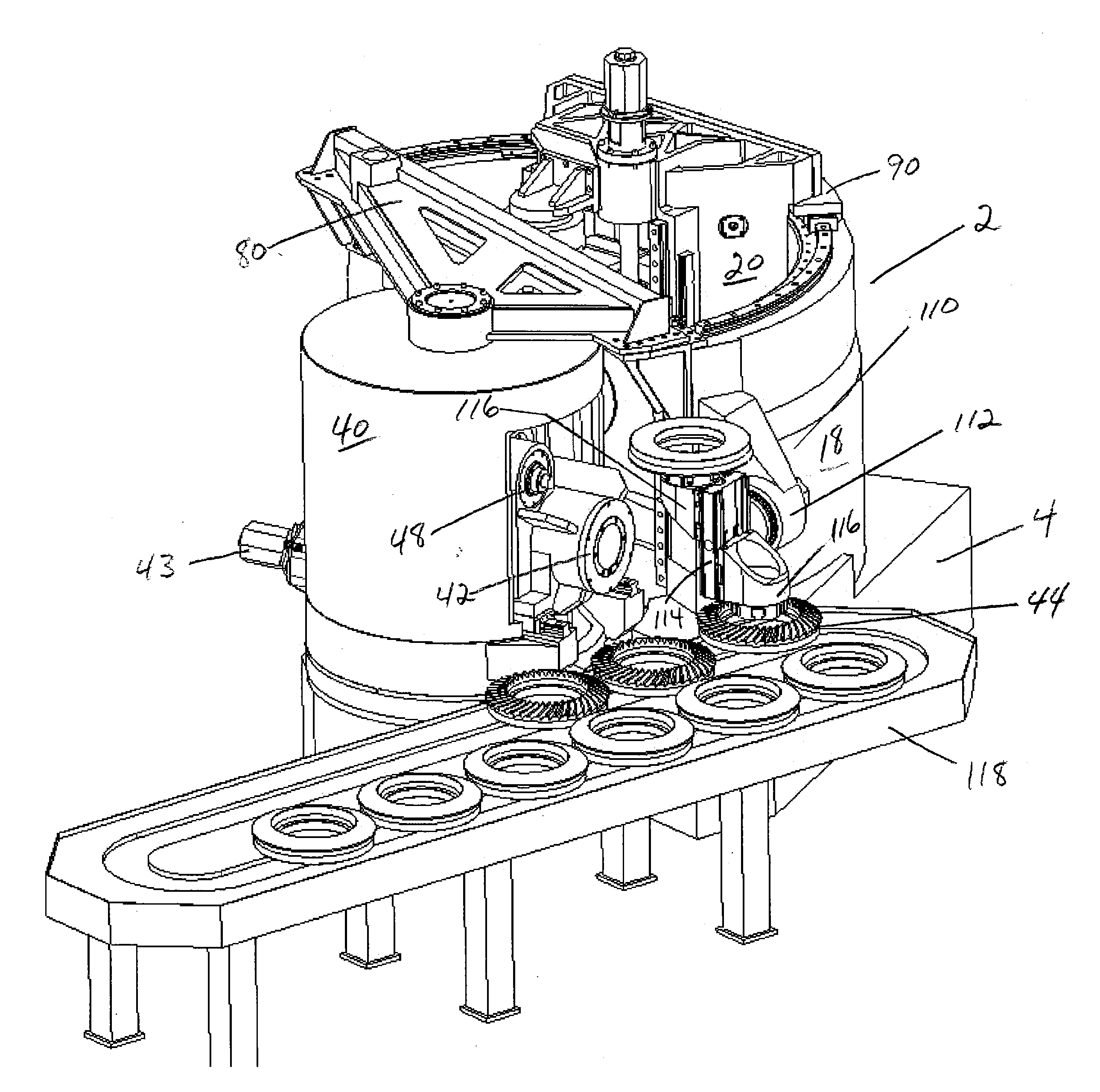
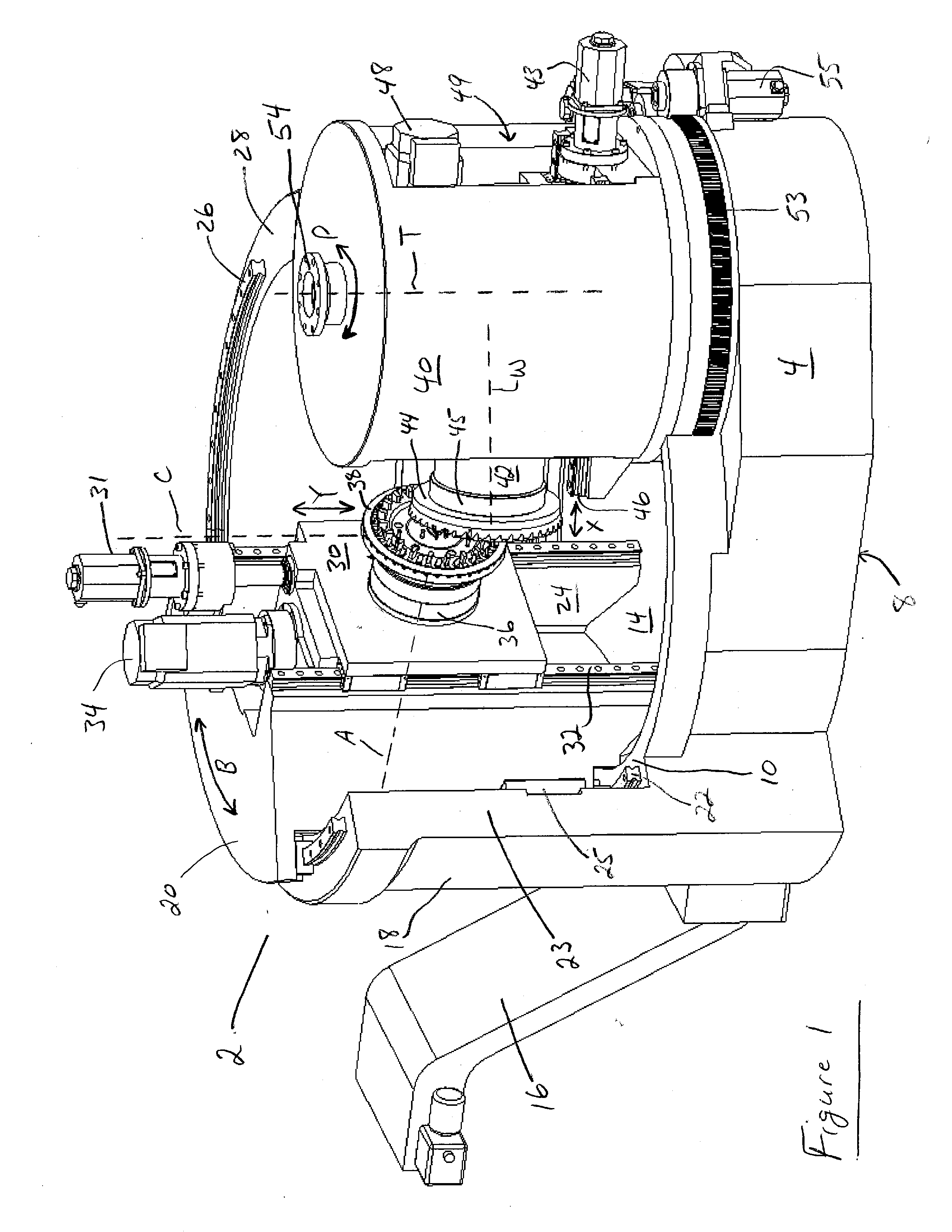
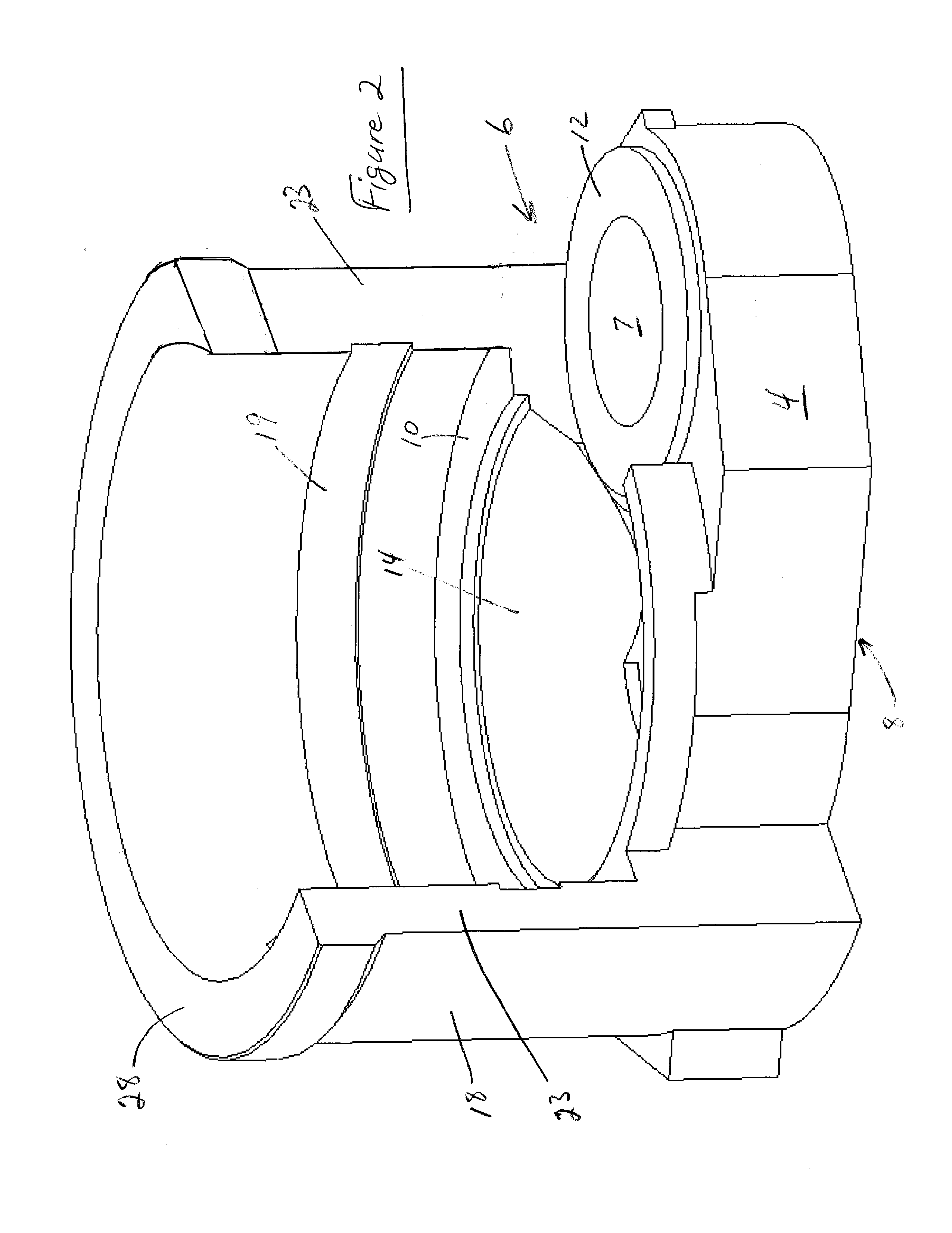
[0026]The details of the invention will now be discussed with reference to the accompanying drawings which illustrate the invention by way of example only. In the drawings, similar features or components will be referred to by like reference numbers. For a better understanding of the invention and ease of viewing, doors a...


PUM

PropertyMeasurementUnit
axis of rotationaaaaaaaaaa
rotationaaaaaaaaaa
curved shapeaaaaaaaaaa

Abstract

A machine tool comprising a machine base having a first side comprising a first planar surface and a machine column movable along an arcuate path on the first planar surface. The machine further comprises a first spindle movable in a first linear direction and being rotatable about a first axis of rotation. The machine further comprises a machine turret located on a second planar surface of the machine base first side. The machine turret is angularly movable about a pivot axis. The machine turret includes a second spindle positioned within the turret with the second spindle being rotatable about a second axis of rotation and being movable in a second linear direction.

Description

[0001]This application claims the benefit of U.S. Provisional Patent Application No. 61 / 569,836 filed Dec. 13, 2011 the entire disclosure of which is hereby incorporated by reference.FIELD OF THE INVENTION[0002]The invention is directed to machine tools and in particular to machines for processing gears such as bevel and hypoid gears.BACKGROUND OF THE INVENTION[0003]Conventional mechanical gear generating machines for producing bevel and hypoid gears by generating or non-generating processes comprise a work support mechanism and a cradle mechanism. During a generating process, the cradle carries a circular tool along a circular path about an axis known as the cradle axis. The cradle represents the body of a theoretical generating gear and the cradle axis corresponds to the axis of the theoretical generating gear. The tool represents one or more teeth on the generating gear. The work support orients a workpiece relative to the cradle and rotates it at a specified ratio to the cradle ...

Claims


Application Information

Patent Timeline
Patent Type & Authority Applications(United States)
IPC IPC(8): B23F17/00
CPCB23F17/00B23F9/10B23F9/105B23Q2210/006B23Q1/4804B23Q1/5468Y10T409/105883B23Q1/5487B23Q7/03B23Q11/0053B23Q11/0057B23Q11/0833B23Q1/5475B23F9/14B23F23/02Y02P70/171Y10T409/103975Y10T409/104611Y10T409/305656Y10T409/305712Y10T409/305768
Inventor GLASOW, KENNETH E.MCGLASSON, WILLIAM D.
Owner GLEASON WORKS
Why Eureka
Try Eureka