Systems and methods for controlling operation of negative pressure wound therapy apparatus

a negative pressure wound and operation system technology, applied in the direction of intravenous devices, suction drainage containers, other medical devices, etc., can solve the problems of unsatisfactory results, unsatisfactory effects, and need for costly replacemen

Active Publication Date: 2013-06-13
SMITH & NEPHEW INC
View PDF4 Cites 118 Cited by
  • Summary
  • Abstract
  • Description
  • Claims
  • Application Information

AI Technical Summary

Benefits of technology

[0029]According to some embodiments, an overall apparatus for the provision of TNP therapy to a patient in almost any environment is provided. The apparatus is lightweight, may be mains or battery powered by a rechargeable battery pack contained within a device (henceforth, the term “device” is used to connote a unit which may contain all of the control, power supply, power supply recharging, electronic indicator means and means for initiating and sustaining aspiration functions to a wound and any further necessary functions of a similar nature). When outside the home, for example, the apparatus may provide for an extended period of operation on battery power and in the home, for example, the device may be connected to the mains by a charger unit whilst still being used and operated by the patient.

Problems solved by technology

However, the above apparatus and methods are generally only applicable to a patient when hospitalized as the apparatus is complex, needing people having specialist knowledge in how to operate and maintain the apparatus, and also relatively heavy and bulky, not being adapted for easy mobility outside of a hospital environment by a patient, for example.
It will be appreciated that with prior known pump units a problem is that as the pump wears over time or when certain environmental factors change, the pressure and flow rate provided by the pump can vary which can cause complications or non-ideal environments.
Also with prior known TNP units the control of pressure particularly on ‘start-up’ of the TNP system or when a new desired pressure is entered by a user can lead to undesirable effects.
For example under certain circumstances prior known control mechanisms drive a pump too hard which can damage pump components and thus lead to the need for costly replacement.
Also during use a rapid increase or decrease in pump speed can often lead to audible effects.
This can concern a user who may think that the TNP system is faulty.
Still further rapid changes can lead to pressure ‘over shooting’ a target value which can lead to increased pain and on occasions bleeding.
A rapid change in pressure resulting in pain and discomfort to a patient may lead to immediate fear and rejection by the patient.
Another problem which can occur is that when a canister utilized to filter and store waste product becomes full correct operation of the TNP system can be impeded.
In common with most prior art TNP therapy apparatus, the apparatus described cannot differentiate between a blocked or kinked aspiration conduit leading from a dressing to a waste canister and a blockage of the canister itself due to it being full, for example.
The alarm to the user on this apparatus can be caused by a number of different faults or conditions.
It will be appreciated that the use of two such sensors is both expensive and prone to error and requires complex processing elements to determine when a canister is full.
The leaks are detected as a failure to achieve any of a plurality of temporary ‘set pressures’.
A flow meter could be used instead to measure flow rate, but is far more costly than utilization of a pressure sensor and a mechanism for determining pump speed.
In some embodiments, when the fluid flow through the apparatus is relatively high and relatively unrestricted, an abnormal burden may be placed on the vacuum pump causing it to operate inefficiently or perhaps necessitating a larger or more powerful than necessary pump to overcome the flow restriction caused by the restrictor.
However, this is not sufficient to be able to distinguish whether the cause of a decrease in aspirant fluid flow rate is a full waste canister or a blocked aspirant conduit.
If, however, the blockage is due to a full waste canister or a blocked waste canister filter adjacent the fluid outlet port in the waste canister then opening the valve will have little or no effect on the fluid flow rate through the fluid flow path.

Method used


Image

  • Systems and methods for controlling operation of negative pressure wound therapy apparatus
  • Systems and methods for controlling operation of negative pressure wound therapy apparatus
  • Systems and methods for controlling operation of negative pressure wound therapy apparatus

Examples


third embodiment

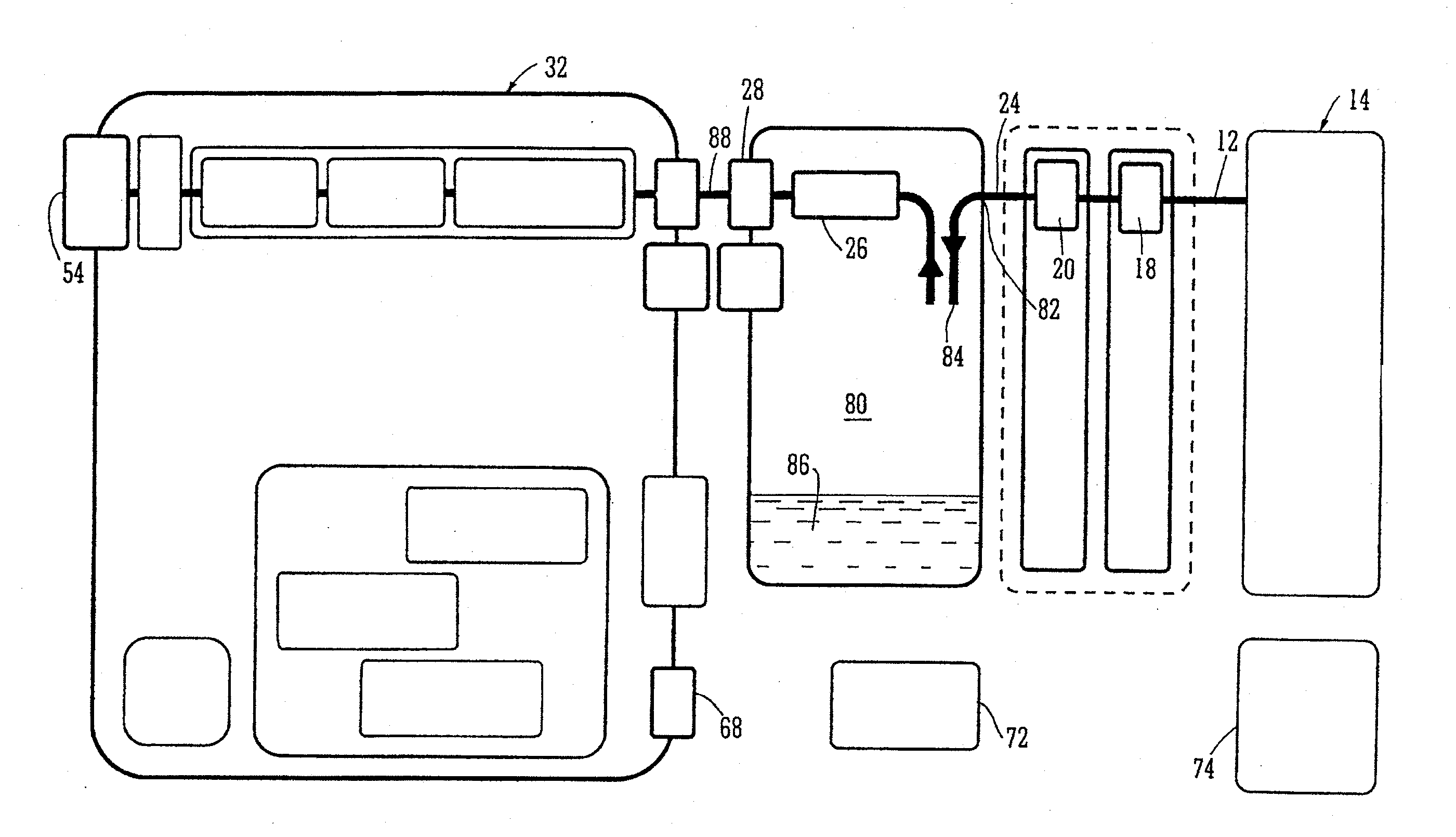
[0214]FIG. 20C shows a third embodiment where two pressures sensors 2040, 2042 are placed upstream of the pump 44 and between the pump 44 and flow restriction 2002. When the canister becomes full or the aspiration conduit blocked, pressure in the tubing 2000 will still be a negative pressure (below ambient atmospheric) and the pressure sensor 2040 will show a negative pressure. However, due to little or no flow of aspirant fluid through the pump 44, the pressure sensor 2042 will show effectively ambient atmospheric pressure which will pertain through the exhaust system to the exhaust aperture 54. Thus, if the pressure differential between sensors 2040 and 2042 signaled to the control system 60 is a negative differential the control system 60 will still activate the alarm. In reality the pressure differential is always likely to be negative since the pressure read by sensor 2040 will be in the region of −50 to −200 mm Hg, i.e. the negative pressure being applied at the wound site / dre...

fourth embodiment

[0215]FIG. 20D shows a fourth embodiment where the flow restrictor 2002 is placed between the canister 22 and pump 44 with pressure sensors 2050, 2052 placed between the canister and flow restrictor and between the flow restrictor and pump, respectively. When aspirant fluid flow through the restrictor 2002 falls to zero due to a full canister or blocked conduit, the two pressure sensors 2050, 2052 will both have the same reading albeit both reading a negative pressure as the pump is still running. Thus, equal or pressure signals less than a stored difference to the control system 60 will result in the alarm being activated.

fifth embodiment

[0216]FIG. 20E shows a schematic diagram of a fifth embodiment where a flow restrictor 2002 is placed downstream of the pump 44 and which has pressure sensors 2060, 2062 placed either side as in FIG. 10, for example, however, in this embodiment, there is a bypass conduit 2064 placed across the flow restrictor, the by-pass conduit 2064 having an adjustable pressure sensitive valve 2066 therein. The valve 2066 may be a simple, spring loaded device able to be set to open at a desired specific pressure. Thus, when, for example, there is relatively unrestricted fluid flow through the flow system in the overall apparatus due to the canister being less than full and the aspiration conduits 12, 24 being free and unblocked, the pump will have an unnecessary burden placed upon it due to the flow restrictor 2002 impeding flow and consequently the pump 44 will be operating inefficiently. Under these conditions pressure in the portion of the by-pass conduit 2068 will exceed a pressure set in the...


PUM


Abstract

Methods and apparatuses for detecting full waste canister and/or fluid flow path blockage conditions are disclosed. Also disclosed are methods and apparatuses for controlling a pump. In some embodiments, flow of fluid can be restricted in a portion of the fluid flow path. A controller can be configured to compare a difference in pressure values upstream and downstream of a fluid flow restrictor to a pressure difference threshold, and determine based on the comparison whether to activate an alarm indicating the full waste canister condition or the fluid flow path blockage condition. The controller can be additionally or alternatively configured to determine a fluid flow using a flow meter, open a selectable valve in response to a comparison of the fluid flow with a fluid flow threshold, determine fluid flow after opening the valve, and determine based on the fluid flow after opening the valve whether to activate the alarm.

Description

CROSS-REFERENCE TO RELATED APPLICATIONS[0001]This application is a continuation-in-part of U.S. application Ser. No. 12 / 667,228, filed on Dec. 29, 2009, which is a U.S. National Phase of the PCT International Application No. PCT / GB2008 / 050507, filed on Jun. 27, 2008, designating the U.S. and published on Jan. 8, 2009 as WO 2009 / 004367, which claims priority to Great Britain Patent Application No. 0712736.8, filed on Jul. 2, 2007. This application is also a continuation-in-part of U.S. application Ser. No. 12 / 667,231, filed on Jun. 30, 2010, which is a U.S. National Phase of the PCT International Application No. PCT / GB2008 / 002118, filed on Jun. 20, 2008, designating the U.S. and published on Jan. 8, 2009 as WO 2009 / 004291, which claims priority to Great Britain Patent Application No. 0712759.0, filed on Jul. 2, 2007. This application is also a continuation-in-part of U.S. application Ser. No. 12 / 667,326, filed on Jul. 6, 2010, which is a U.S. National Phase of the PCT International A...

Claims


Application Information

Patent Timeline
Patent Type & Authority Applications(United States)
IPC IPC(8): A61M1/00
CPCA61M1/0001A61M1/0049A61M1/0088A61M1/0052A61M2205/18A61M2205/3331A61M2205/3334A61M2205/15A61M1/78A61M1/784A61M2205/42A61M1/984A61M1/96A61M1/982A61M1/962A61M1/60A61M2205/3365A61M2205/50A61M2205/502A61M2205/7536A61M2205/8206A61M2209/088
Inventor GORDON, BENJAMINTURNER, JAKEHARTWELL, EDWARDJACOB, STEPHENWRENCH, NATHANVERNON-HARCOURT, EDWARDHARRIS, DAVID
Owner SMITH & NEPHEW INC
Why Eureka
Try Eureka