High-frequency transformer, high-frequency component, and communication terminal device

Active Publication Date: 2013-06-20
MURATA MFG CO LTD
View PDF2 Cites 12 Cited by
  • Summary
  • Abstract
  • Description
  • Claims
  • Application Information

AI Technical Summary

Benefits of technology

The present invention provides a high-frequency transformer with a small leakage magnetic field and a high coupling coefficient between a primary coil and a secondary coil. This is achieved without using a material with high saturation magnetic flux density or magnetic permeability. The high-frequency transformer includes a laminated body with a plurality of base material layers, and a primary coil and a secondary coil embedded in the laminated body. The primary coil includes an odd-numbered coil conductor pattern and an even-numbered coil conductor pattern, which are wound in opposite directions to each other. The secondary coil includes an odd-numbered coil conductor pattern and an even-numbered coil conductor pattern, which are also wound in opposite directions to each other. The directions of the magnetic field occurring in the first axis and the second axis are opposite to each other. The high-frequency transformer is suitable for use in high-frequency components and communication terminal devices.

Problems solved by technology

While a typical high-frequency transformer is formed by wrapping a primary coil and a secondary coil, which are made of metal wires, around a magnetic core made of ferrite or magnetic metal, it has been difficult for such a structure to be miniaturized.
One shortcoming of the above-described sheet multilayer process is that there is a limit as to available materials which can be used.
In other words, it is difficult to make green sheets using a magnetic material whose saturation magnetic flux density or magnetic permeability is high, and it is difficult to subject the green sheets to co-firing along with a conductor pattern material.
Therefore, it is difficult to use a magnetic material whose saturation magnetic flux density or magnetic permeability is high, and it is difficult to obtain a high-frequency transformer having a high coupling coefficient and a low loss.

Method used


Image

  • High-frequency transformer, high-frequency component, and communication terminal device
  • High-frequency transformer, high-frequency component, and communication terminal device
  • High-frequency transformer, high-frequency component, and communication terminal device

Examples


first preferred embodiment

[0027]A laminated type transformer of a first preferred embodiment of the present invention is a laminated type transformer preferably used for a high-frequency circuit in a communication terminal device or other suitable device, for example, and preferably configured as a chip-type component mountable on a surface of a printed wiring board or other suitable substrate, for example.

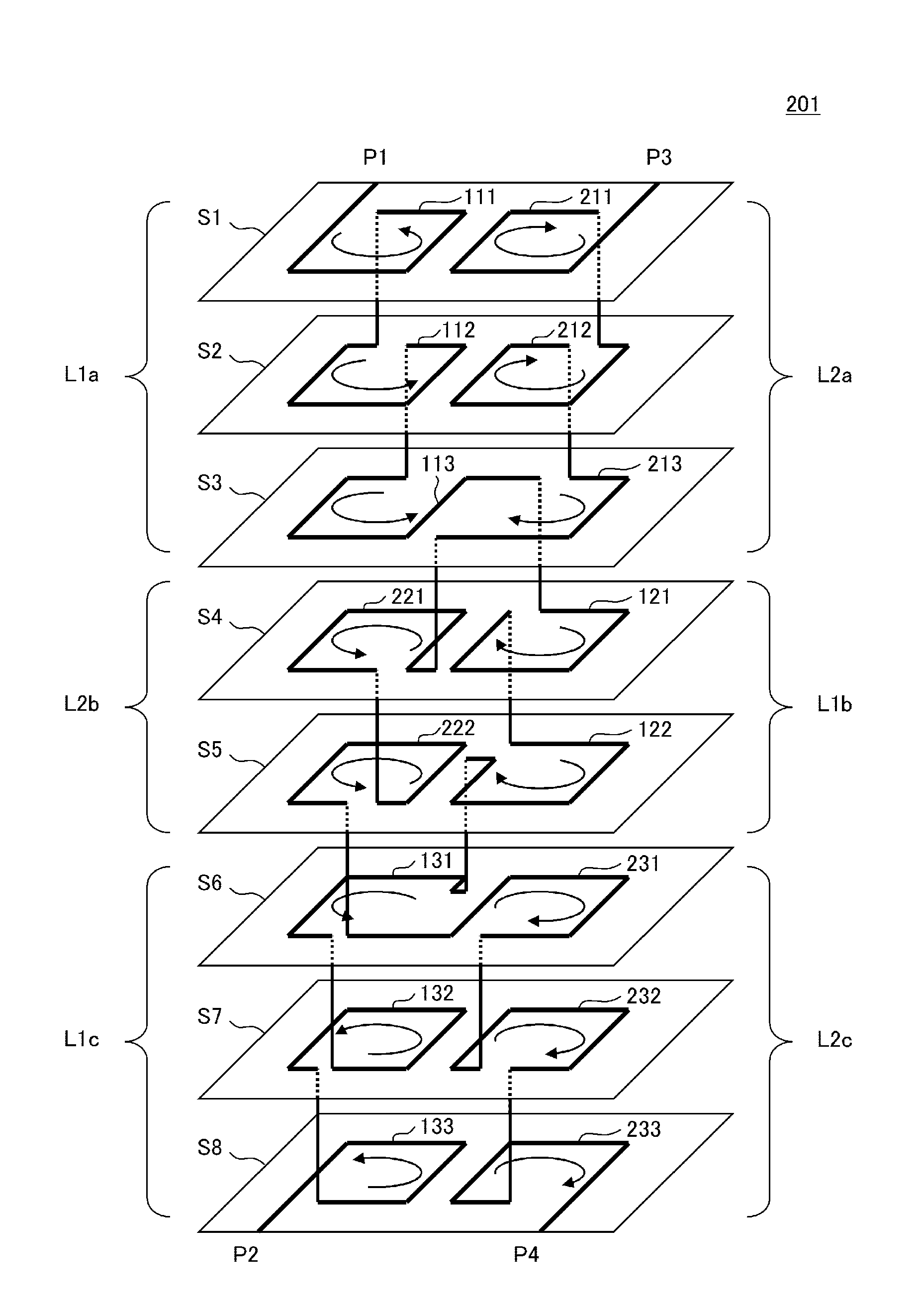
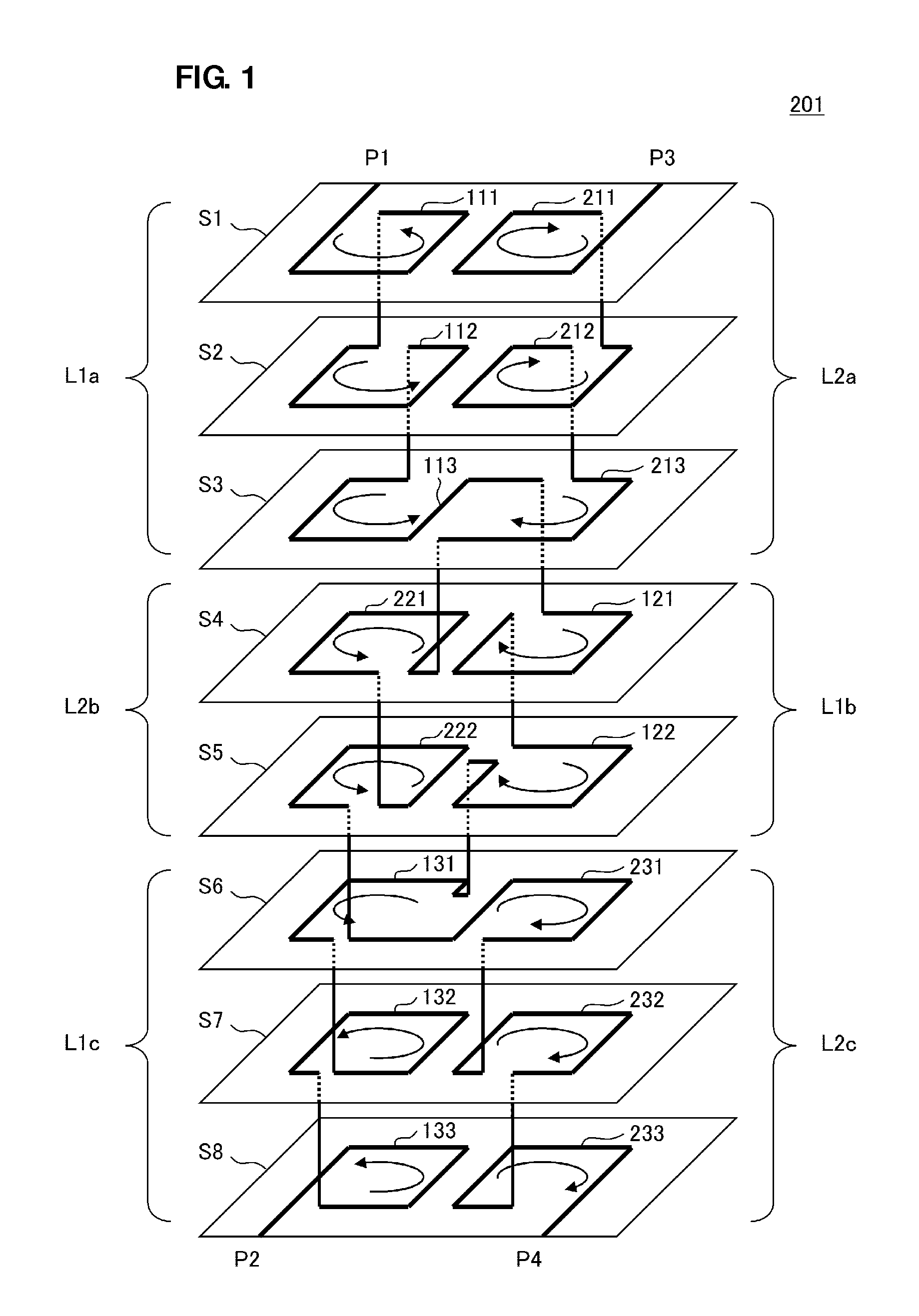
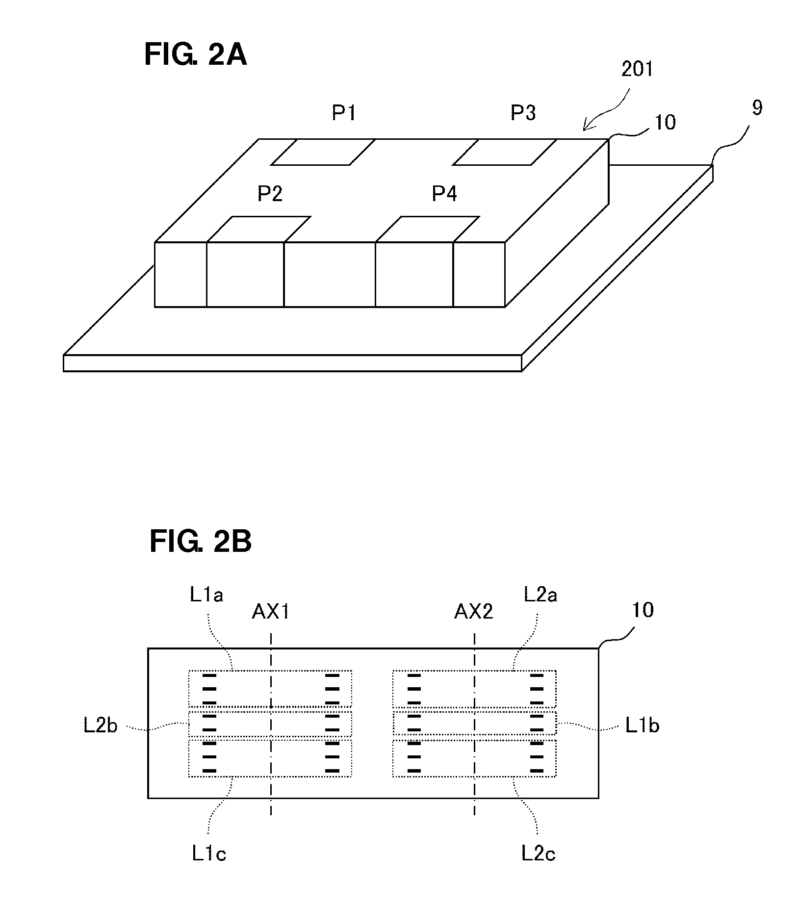
[0028]FIG. 1 is the exploded perspective view of a high-frequency transformer 201 of the first preferred embodiment. FIG. 2A is a perspective view in a state in which the high-frequency transformer 201 of the first preferred embodiment is mounted on a printed wiring board 9. FIG. 2B is the cross-sectional view of the high-frequency transformer 201.

[0029]In the high-frequency transformer 201, a primary coil and a secondary coil are provided in a laminated body 10 including a plurality of base material layers S1 to S8 that are laminated to one another and a plurality of conductor patterns provided in the lam...

second preferred embodiment

[0047]While, in the first preferred embodiment, the primary coil preferably includes three series-connected coil conductor patterns and the secondary coil similarly preferably includes three series-connected coil conductor patterns, a second preferred embodiment of the present invention illustrates an example in which each of a primary coil and a secondary coil preferably includes two coil conductor patterns.

[0048]FIG. 4 is the exploded perspective view of a high-frequency transformer 202 of the second preferred embodiment. FIG. 5A is a perspective view in a state in which the high-frequency transformer 202 of the second preferred embodiment is mounted on the printed wiring board 9. FIG. 5B is the cross-sectional view of the high-frequency transformer 202.

[0049]In the high-frequency transformer 202, a primary coil and a secondary coil are provided in a laminated body including a plurality of base material layers S1 to S6 that are laminated to one another and a plurality of conductor...

third preferred embodiment

[0061]FIG. 7A is the schematic plan view of a high-frequency transformer 203 of a third preferred embodiment of the present invention and a diagram illustrating a positional relationship between coil conductor patterns within a laminated body. FIG. 7B is the cross-sectional view of the high-frequency transformer 203.

[0062]As illustrated in FIG. 7A and FIG. 7B, the coil apertures of the first coil conductor pattern L1a and the third coil conductor pattern L1c of the primary coil include a first axis AX1, and the coil aperture of the second coil conductor pattern L1b of the primary coil includes a second axis AX2 parallel or approximately parallel to the first axis AX1. In addition, the coil apertures of the first coil conductor pattern L2a and the third coil conductor pattern L2c of the secondary coil include the second axis AX2, and the coil aperture of the second coil conductor pattern L2b of the secondary coil includes the first axis AX1.

[0063]However, the coil axis AX11 of the fi...


PUM


Abstract

In a high frequency transformer, when a current flows between input-output ports, a magnetic flux produced by first and third coil conductor patterns of a primary coil is interlinked with a second coil conductor pattern of a secondary coil. A magnetic flux produced by the second coil conductor pattern of the primary coil is interlinked with the first and third coil conductor patterns of the secondary coil. The coil conductor patterns are wound so that when a current flows through a transformer, the directions of magnetic fields occurring within the first and third coil conductor patterns of the primary coil and the second coil conductor pattern of the secondary coil are the same and the directions of magnetic fields occurring within the first and third coil conductor patterns of the secondary coil and the second coil conductor pattern of the primary coil are the same.

Description

BACKGROUND OF THE INVENTION[0001]1. Field of the Invention[0002]The present invention relates to a high-frequency transformer in which coil elements are coupled to each other with a high degree of coupling, and a high-frequency component and a communication terminal device which including such a high frequency transformer.[0003]2. Description of the Related Art[0004]While a typical high-frequency transformer is formed by wrapping a primary coil and a secondary coil, which are made of metal wires, around a magnetic core made of ferrite or magnetic metal, it has been difficult for such a structure to be miniaturized.[0005]On the other hand, for example, as described in Japanese Unexamined Patent Application Publication No. 2002-057042 or International Publication No. WO 2008 / 105213, a laminated high-frequency transformer has been known to include a primary coil and a secondary coil, formed by printing a conductor pattern of silver, copper, or other metal in a laminated body formed by ...

Claims


Application Information

Patent Timeline
IPC IPC(8): H01F27/28
CPCH01F27/2804H01F2027/2809H01F19/04
Inventor KATO, NOBORU
Owner MURATA MFG CO LTD
Why Eureka
Try Eureka