Variable reluctance resolver

a resolver and variable technology, applied in the field of vr resolvers, can solve the problems of dimensional accuracy degradation, housing function cannot be provided in the vicinity of the terminal base portion, space cannot be provided, etc., and achieve the effect of convenient coaxial mounting

Active Publication Date: 2013-06-27
MINEBEAMITSUMI INC
View PDF7 Cites 13 Cited by
  • Summary
  • Abstract
  • Description
  • Claims
  • Application Information

AI Technical Summary

Benefits of technology

[0013]According to the present invention, a VR resolver having a main body that is combined with a housing is provided. The VR resolver d

Problems solved by technology

However, there may be cases in which the space cannot be provided when the resolver is mounted in a limited space such as in an automobile.
Therefore, the housing function cannot be provided in the vicinity of the terminal base portion that is a connection to the

Method used


Image

  • Variable reluctance resolver
  • Variable reluctance resolver
  • Variable reluctance resolver

Examples


Embodiment Construction

Structure

[0022]An embodiment of the present invention will be described with reference to the figures hereinafter.

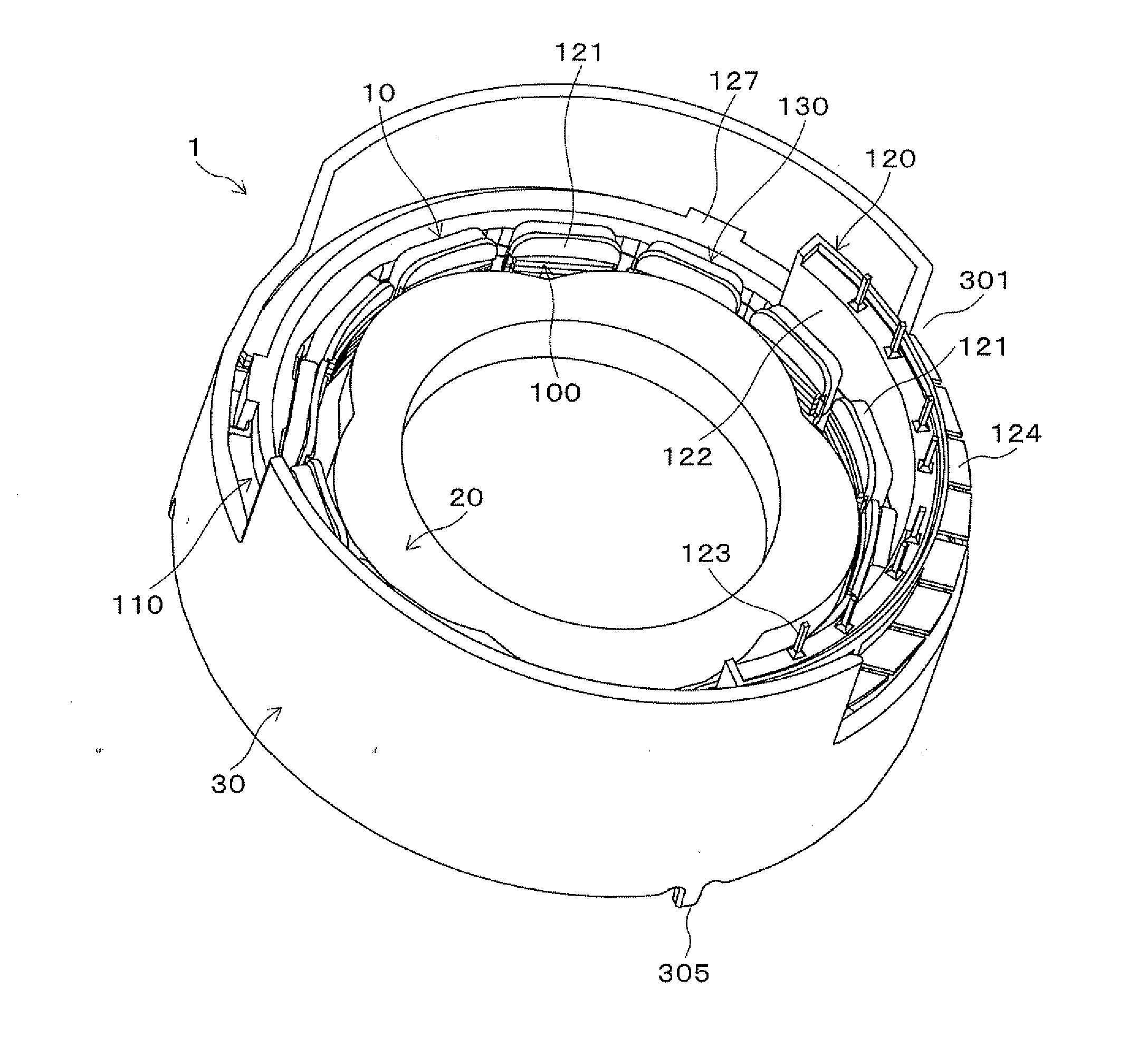
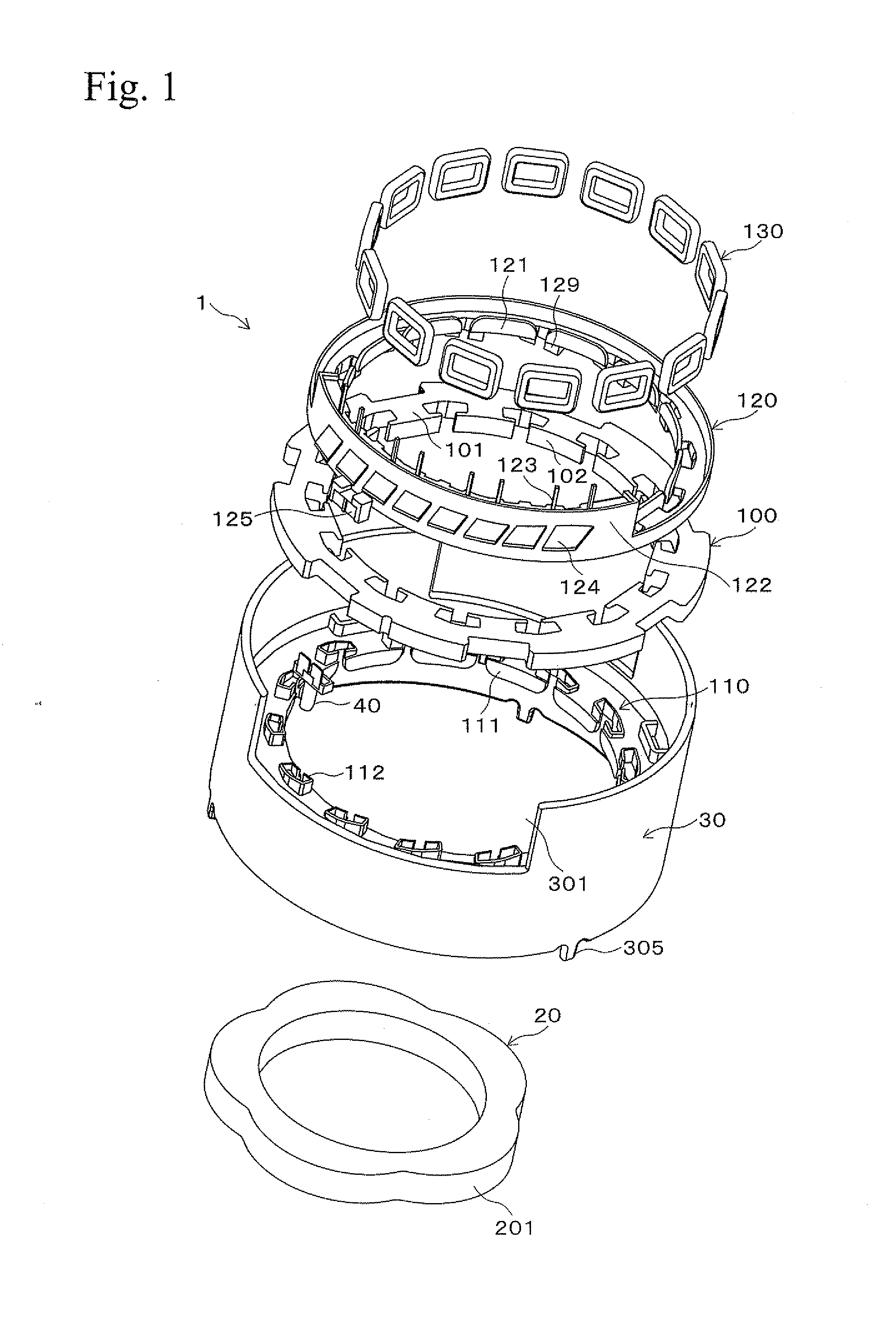
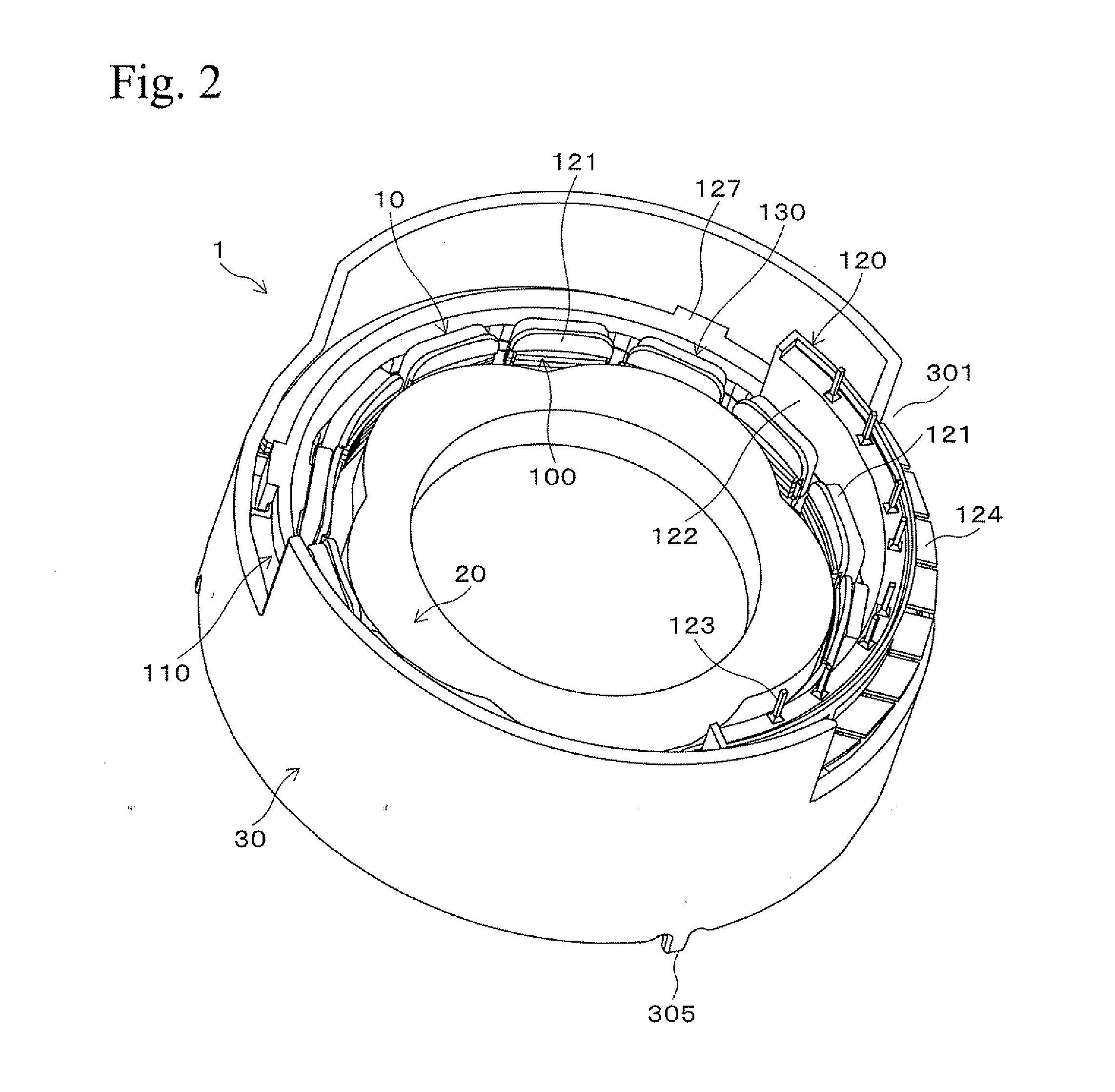
[0023]FIG. 1 is an exploded perspective view of a VR resolver (hereinafter called a “resolver”) 1 relating to an embodiment of the present invention. FIGS. 2 and 3 are a perspective view and a side view of the resolver 1 in a combined condition, respectively. The resolver 1 of an embodiment is formed of a ring-like stator 10, a ring-like rotor 20 that is arranged inside the stator 10, and a cylindrical housing 30 that accommodates the stator 10. The stator 10 has a stator core 100, two insulators, that is, a first insulator 110 and a second insulator 120, and coils 130. The first insulator 110 and the second insulator 120 are combined so as to hold the stator core 100 therebetween from both sides of the stator core 100 in an axial direction. The stator core 100 is formed with plural salient poles 101, and the coils 130 are wound to the salient poles 101 of the stator cor...


PUM


Abstract

A variable reluctance resolver has a stator combined with a housing. The resolver does not require extra space in a case for a device, into which the resolver is mounted, and it is easily coaxially mounted to the device. The resolver includes a ring-like stator 10, a rotor 20, and a housing 30. The stator 10 has a stator core 100, a first insulator 110, a second insulator 120, and coils 130. The stator core 100 is provided with plural salient poles 101. The first insulator 110 and the second insulator 120 hold the stator core 100 therebetween from both sides of the stator core 100. The coils 130 are wound to the salient poles 101 via the first insulator 110 and the second insulator 120. The housing 30 accommodates the stator 10. The first insulator 110 is coaxially integrally formed with the housing 30.

Description

BACKGROUND OF THE INVENTION[0001]1. Field of the Invention[0002]The present invention relates to a VR resolver (Variable Reluctance resolver) that may be used for measuring a rotation angle of a motor.[0003]2. Description of Related Art[0004]In general, VR resolvers are formed primarily of a ring-like stator and a rotor that is arranged inside the stator. The stator has a ring-like stator core, a first insulator and a second insulator that have electric insulating characteristics, and coils. The stator core is formed by laminating plural circular yoke sheet members that are obtained by press cutting soft magnetic materials. The stator core is held between the first insulator and the second insulator from both end surfaces of the stator core. The stator core is formed with plural salient poles at an inner circumferential surface thereof, and the coils are wound to the salient poles via the first insulator and the second insulator.[0005]Such a resolver may be inserted and mounted in a...

Claims


Application Information

Patent Timeline
IPC IPC(8): G01B7/30
CPCG01D5/2046G01B7/30
Inventor OCHIAI, TAKAAKISHIRAYANAGI, SHUUMEI
Owner MINEBEAMITSUMI INC
Why Eureka
Try Eureka