Linear rotation mechanism for hemostasis clip device and other devices

Active Publication Date: 2013-07-04
BOSTON SCI SCIMED INC
View PDF8 Cites 93 Cited by
  • Summary
  • Abstract
  • Description
  • Claims
  • Application Information

AI Technical Summary

Problems solved by technology

Manipulation of the hemostasis device about a portion of target tissue is often difficult and may require extensive effort including attempts to rotate the hemostasis device relative to the target tissue to achieve proper positioning of the clip to en

Method used


Image

  • Linear rotation mechanism for hemostasis clip device and other devices
  • Linear rotation mechanism for hemostasis clip device and other devices
  • Linear rotation mechanism for hemostasis clip device and other devices

Examples


Embodiment Construction

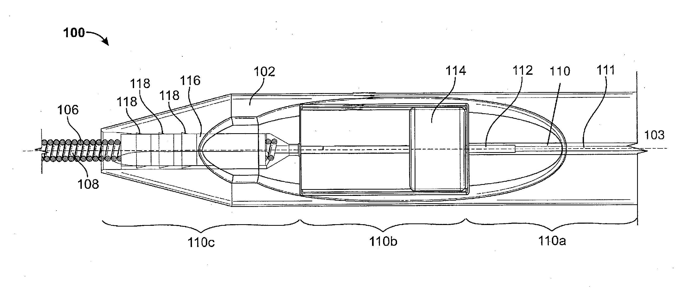
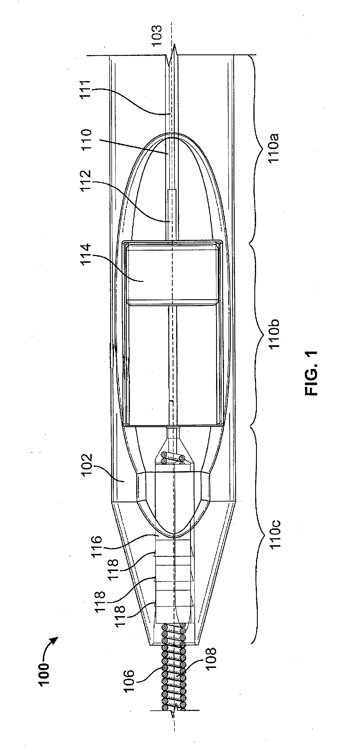
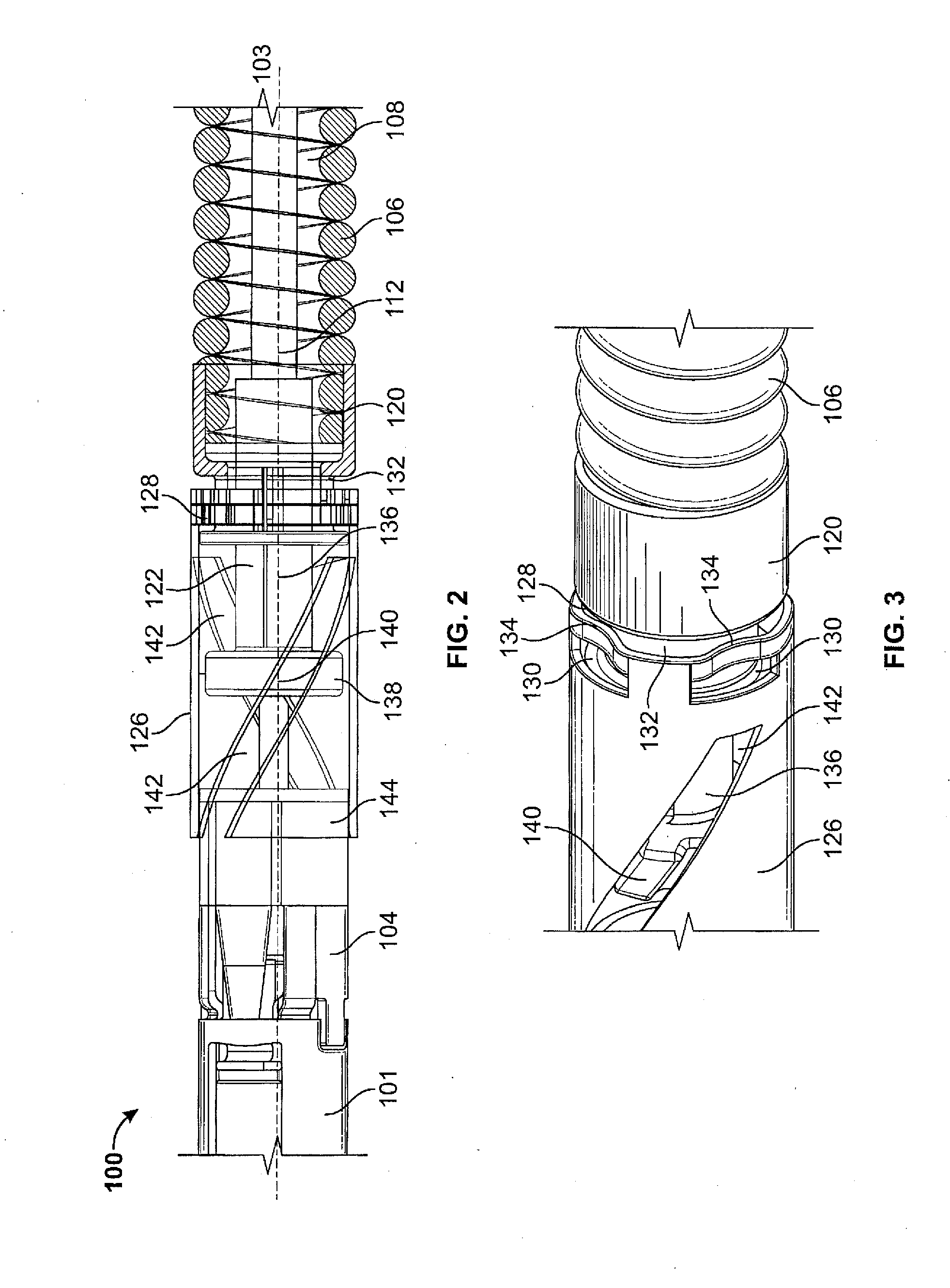
[0008]The present invention may be further understood with reference to the following description and the appended drawings, wherein like elements are referred to with the same reference numerals. The present invention relates to a device enabling rotation of an end effector attached to a flexible endoscopic device. In one embodiment of the invention, the end effector is a device for applying one or more hemostatic clips. The exemplary device according to the invention permits rotation of the clip(s) to aid in positioning thereof relative to target tissue. Specifically, the exemplary device according to the invention is configured to rotate the clip(s) relative to an outer sheath encasing the clip(s). The rotation mechanism converts an axial force applied at a proximal actuator into a rotational force rotating the clip(s). It is noted that although the rotation mechanism disclosed herein has been described with respect to clipping devices, the rotation mechanism may also be designed...


PUM


Abstract

A medical device includes a handle, a flexible member extending from a proximal end connected to the handle to a distal end, a rotation mechanism connected to the distal end of the flexible member, an end effector coupled to a distal portion of the rotation mechanism and a push member extending through the handle and flexible member and connecting to the rotation mechanism, the rotation mechanism being configured and dimensioned to convert axial movement of the push member into rotation of the end effector.

Description

PRIORITY CLAIM[0001]This application claims the priority to the U.S. Provisional Application Ser. No. 61 / 581,917, entitled “Linear Rotation Mechanism For Hemostasis Clip Device And Other Devices” filed on Dec. 30, 2011. The specification of the above-identified application is incorporated herewith by reference.BACKGROUND[0002]Pathologies of the gastro-intestinal (“GI”) system, the biliary tree, the vascular system and other body lumens are commonly treated through endoscopic procedures, some of which require active and / or prophylactic hemostasis to control internal bleeding. Specialized endoscopic devices are used to deliver the hemostasis devices (e.g., clips) to desired locations within the body and to position and deploy the hemostasis devices at the desired locations. Manipulation of the hemostasis device about a portion of target tissue is often difficult and may require extensive effort including attempts to rotate the hemostasis device relative to the target tissue to achieve...

Claims


Application Information

Patent Timeline
IPC IPC(8): A61B17/10
CPCA61B17/1285A61B2017/0034A61B17/10A61B2017/2929A61B2017/293A61B2017/2905
Inventor HARRIS, COLBY
Owner BOSTON SCI SCIMED INC
Why Eureka
Try Eureka