Eureka AIR delivers breakthrough ideas for toughest innovation challenges, trusted by R&D personnel around the world.

Method and device for detecting a rotational separation adversely affecting a turbine engine compressor

Active Publication Date: 2013-07-25
SN DETUDE & DE CONSTR DE MOTEURS DAVIATION S N E C M A
View PDF3 Cites 9 Cited by
  • Summary
  • Abstract
  • Description
  • Claims
  • Application Information

AI Technical Summary

Benefits of technology

The invention proposes using multiple indicators, such as high engine temperature, increased turbine outlet pressure, and abnormal engine acceleration, to reliably identify a rotating stall in the compressor. This helps optimize the search for the stall and economize engine resources by limiting the execution of the method.

Problems solved by technology

As a general rule, this instability gives rise to a drop in compression characteristics and it is manifested in particular by a drop in the efficiency and in the compression ratio of the compressor.
It is also responsible for major vibratory phenomena that can lead to premature wear of the blades in the compressor.
Nevertheless, most of these methods rely:either on detection techniques that do not make it possible to distinguish between a surging situation and a rotating stall situation.

Method used


Image

  • Method and device for detecting a rotational separation adversely affecting a turbine engine compressor
  • Method and device for detecting a rotational separation adversely affecting a turbine engine compressor
  • Method and device for detecting a rotational separation adversely affecting a turbine engine compressor

Examples


Embodiment Construction

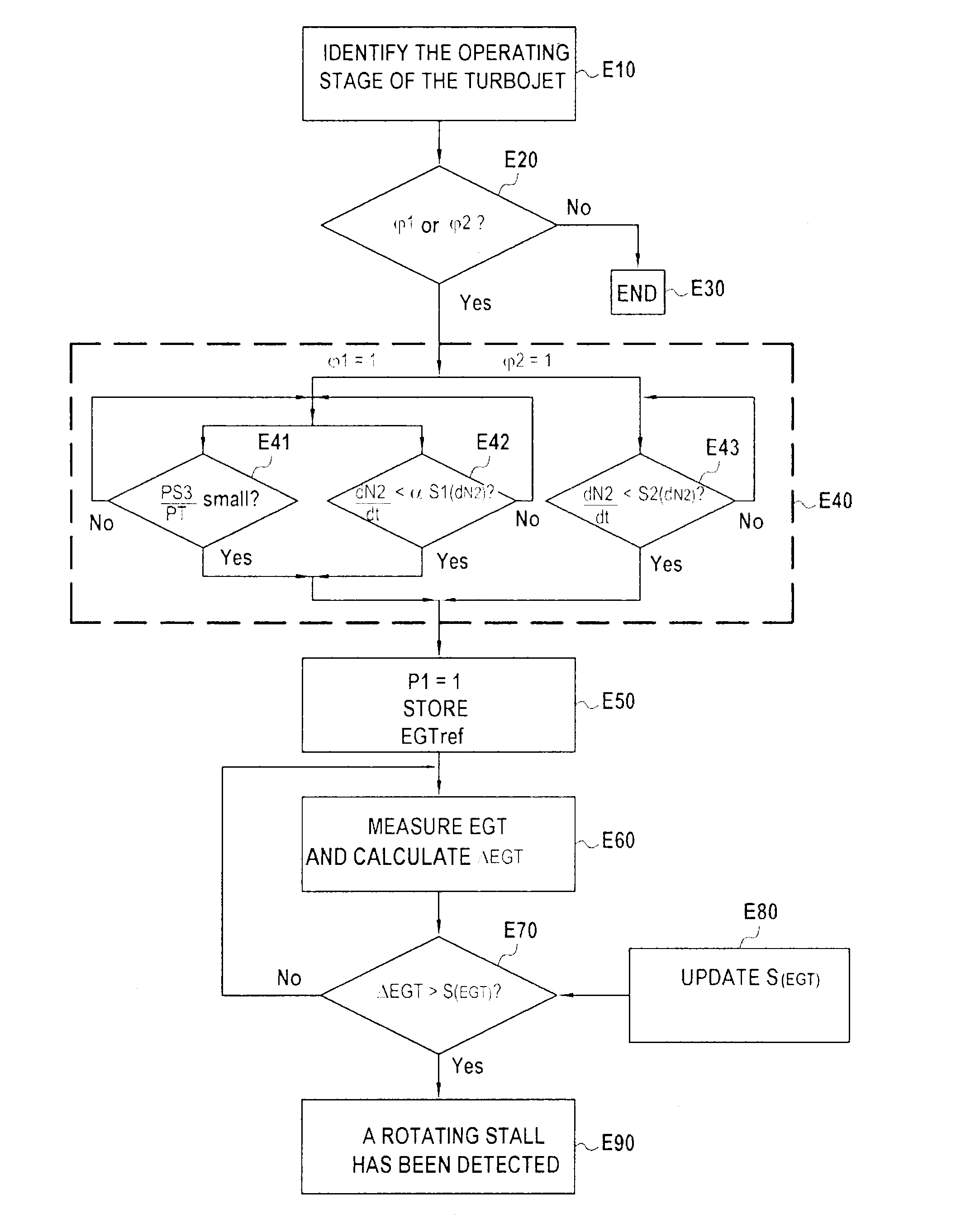
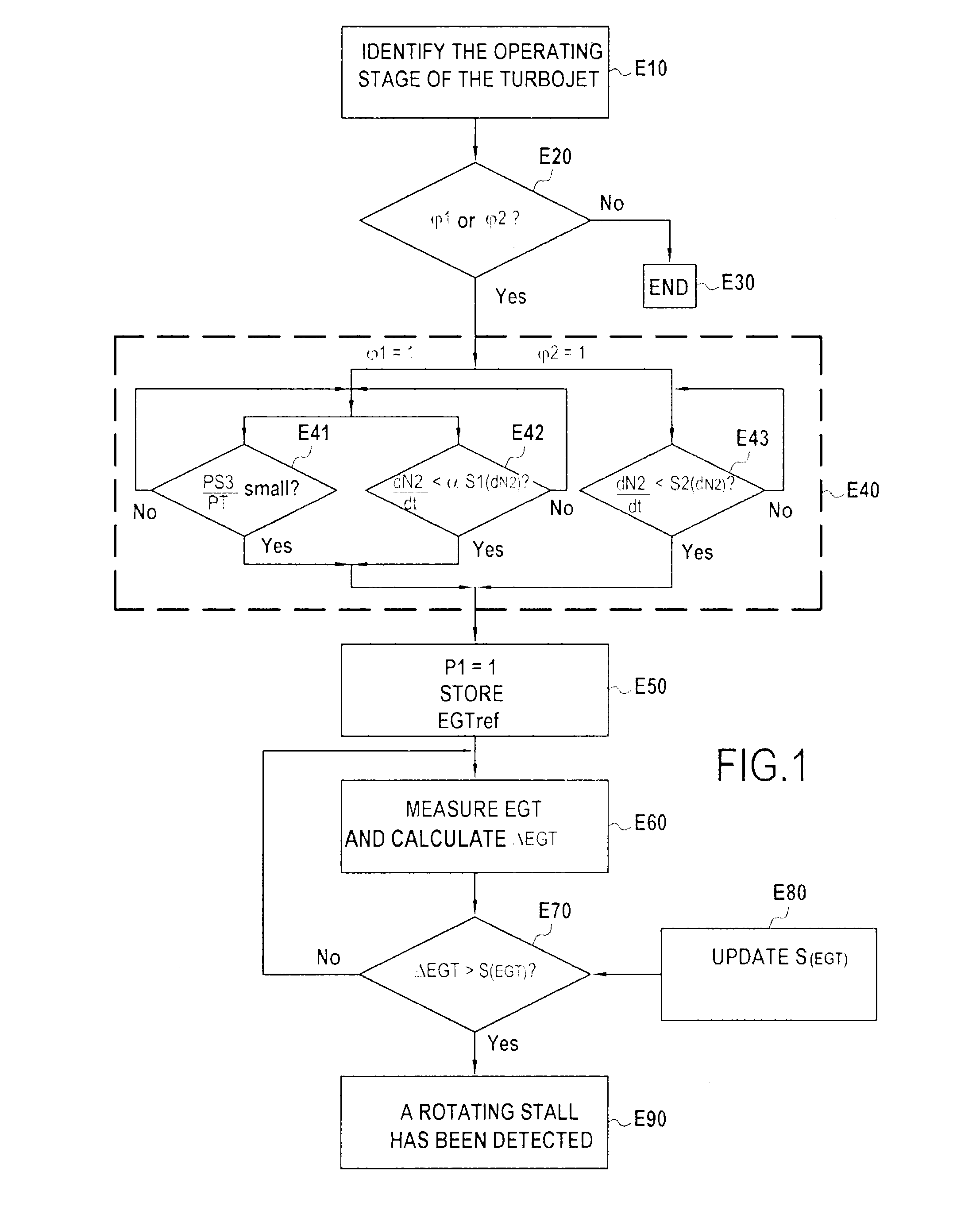
[0071]As mentioned above, the invention proposes applying the principles of fuzzy logic for detecting a rotating stall. More precisely, it advantageously proposes combining a plurality of behavior signatures or indicators of the turbine engine that are all associated with the rotating stall phenomenon, in order to identify the presence of that phenomenon in the compressor in reliable manner.

[0072]The term “behavior signature” is used herein to mean behavior characteristic of an operating parameter of the engine (e.g. engine speed, temperature at the outlet from the turbine, operating line of the compressor, etc.) in the presence of a rotating stall.

[0073]In the implementations described herein, consideration is given to the following indicators:[0074]a stagnation or a drop in engine speed;[0075]an increase of temperature at the outlet from the turbine of the engine;[0076]a drop in compression ratio (surging);[0077]a high temperature at the outlet from the turbine of the engine; and[...


PUM


Abstract

A method and device detecting a rotating stall affecting a turbine engine compressor. The detection method includes: detecting an abnormal acceleration of the engine or an operating line of the compressor that is characteristic of a failure of the engine; storing a reference temperature measured at an outlet from a turbine of the engine at an instant of detection; comparing a determined temperature threshold with the difference between a current temperature at the outlet of the turbine as measured after detection and the reference temperature; and identifying that a rotating stall is present in event of the threshold being exceeded.

Description

BACKGROUND OF THE INVENTION[0001]The present invention relates to the general field of turbine engines. It relates more particularly to detecting a rotating stall affecting a turbine engine compressor.[0002]The invention applies to any type of turbine engine, and in particular to aeroengines such as turbojets, turboprops, etc.[0003]In known manner, a rotating stall is an aerodynamic instability that affects the compressor and that is characterized by the presence of one or more localized pockets of fluid (referred to as stall pockets or cells) that propagate in the circumferential direction of the compressor, at a speed that is generally slower than the speed of rotation of the compressor.[0004]As a general rule, this instability gives rise to a drop in compression characteristics and it is manifested in particular by a drop in the efficiency and in the compression ratio of the compressor. It is also responsible for major vibratory phenomena that can lead to premature wear of the bl...

Claims


Application Information

Patent Timeline
IPC IPC(8): G01M15/14
CPCF01D17/02F01D21/02F02C9/16F04D27/001F05D2270/303F05D2270/707F05D2260/80F05D2270/10F05D2270/304G01M15/14
Inventor DJELASSI, CEDRIK
Owner SN DETUDE & DE CONSTR DE MOTEURS DAVIATION S N E C M A
Why Eureka
Eureka Blog
Learn More