
Electric pencil sharpener with a replaceable cutter assembly

a cutter assembly and electric pencil technology, which is applied in the field of electric pencil sharpeners, can solve the problems of wasting money and usable components in the pencil sharpener, huge inconvenience to users, and difficult to remove the cutter assembly by users, so as to improve the practicality of the electric pencil sharpener, reduce the cost of replacing the cutter assembly, and replace the cutter assembly easy and conveniently

Inactive Publication Date: 2013-07-25
SDI CORPORATION
View PDF4 Cites 10 Cited by
  • Summary
  • Abstract
  • Description
  • Claims
  • Application Information

AI Technical Summary

Benefits of technology

The invention is an electric pencil sharpener with a replaceable cutter assembly. This design makes it easy to replace the worn-off cutter assembly with a new one, which improves the practicality of the electric pencil sharpener and lowers the cost of replacing the cutter assembly. This is because when the cutter is worn off or damaged, the cutter assembly can be easily detached from the cover or the bottom of the waste case and replaced with a new one. It is unnecessary to throw a whole electric pencil sharpener away, so that waste of resources is reduced and the cost for using the electric pencil sharpener is also greatly lowered.

Problems solved by technology

However, the cutter of the conventional electrical pencil sharpener is connected directly with a transmission device for being connected to and driven by a driving device, so the cutter is difficult and even impossible to be detached from the driving device by a user.
When the unchangeable cutter is damaged, the whole pencil sharpener has to be thrown away, and this causes waste of money and usable components in the pencil sharpener.
However, when replacing the cutter, the user not only has to disassemble the electrical pencil sharpener, but also has to demount the worn cutter from the pencil sharpener and then mount a new cutter onto the pencil sharpener by a screw driver or any other tool.
The mounting and demounting of the cutter are both troublesome and time-consuming, causing huge inconvenience to the user.

Method used


Image

  • Electric pencil sharpener with a replaceable cutter assembly
  • Electric pencil sharpener with a replaceable cutter assembly
  • Electric pencil sharpener with a replaceable cutter assembly

Examples


Embodiment Construction

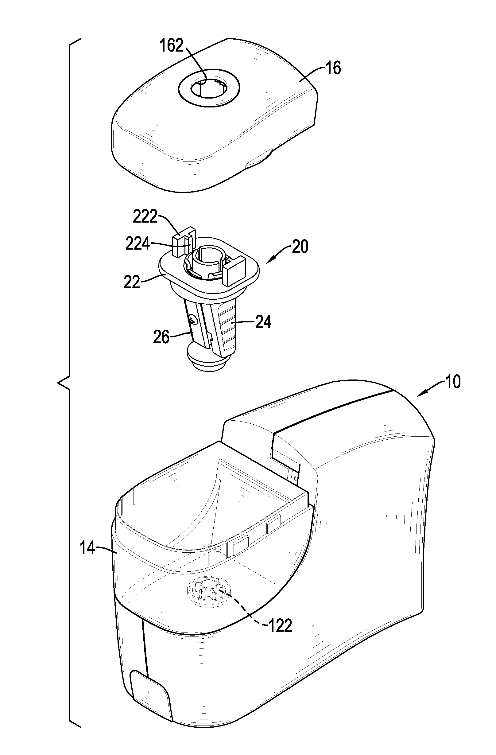
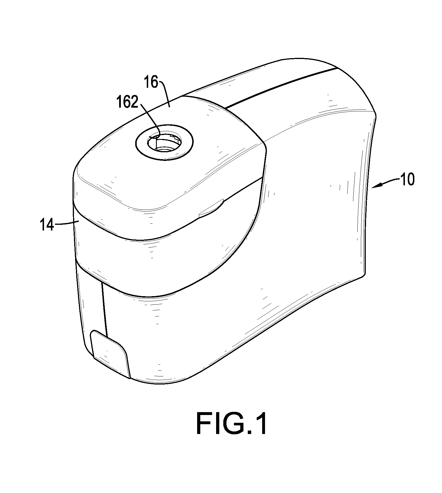
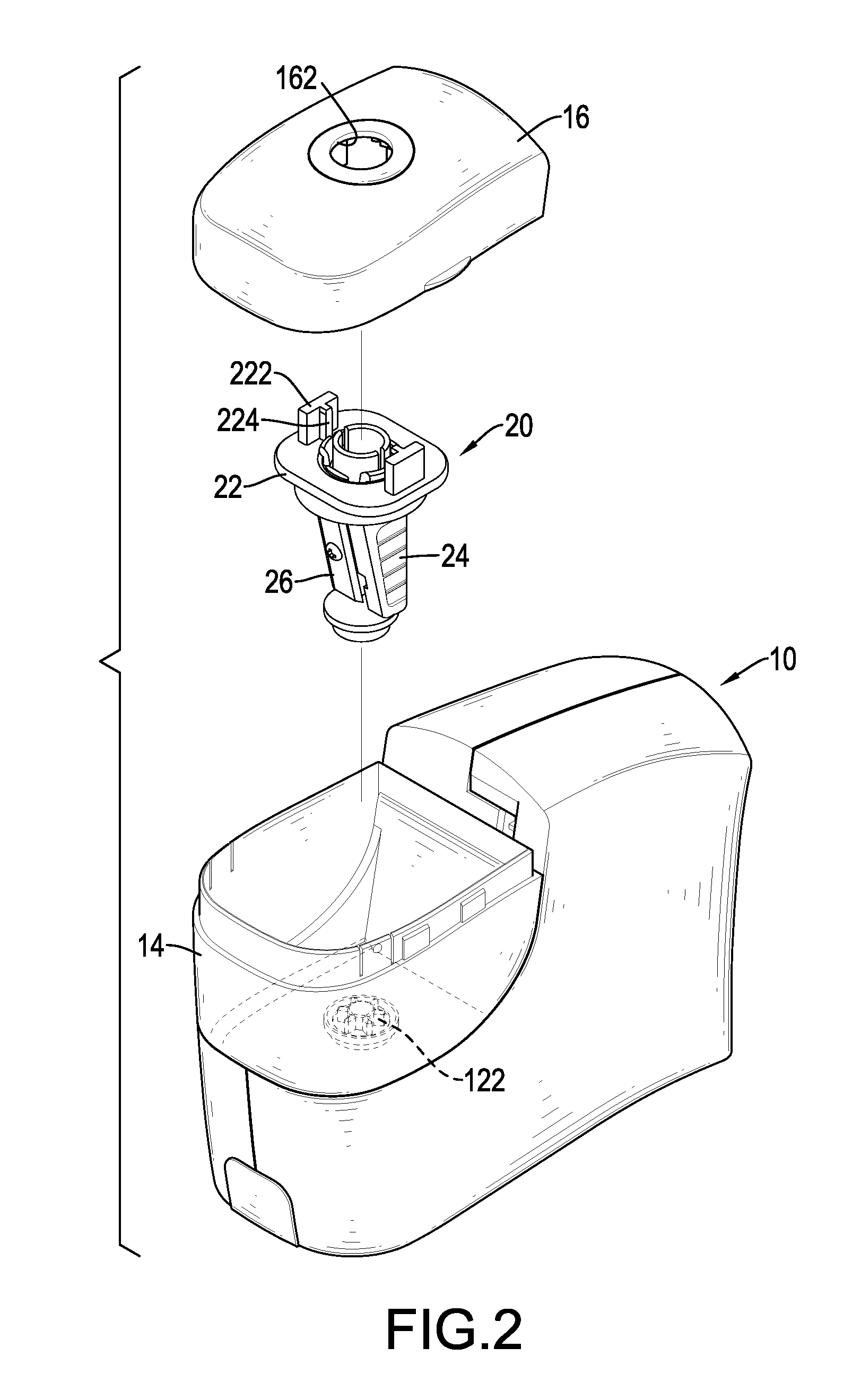
[0023]With reference to FIGS. 1 to 4, an electric pencil sharpener in accordance with the present invention comprises a body 10, a transmission device 12, a waste case 14, a cover 16 and a cutter assembly 20.

[0024]The transmission device 12 is mounted in the body 10, comprises a motor, a power supply and a gear set and may be conventional, so the detail description of the transmission device 12 is omitted. The transmission device 12 has a transmission element 122 mounted inside the waste case 14.

[0025]The waste case 14 is mounted securely or detachably on the body 10 and has an opening defined in the top of the waste case 14. The cover 16 is mounted on and closes the opening of the waste case 14 and has a pencil inserting hole 162 formed through the cover 16.

[0026]With reference to FIGS. 2 to 5, the cutter assembly 20 is mounted in the waste case 14, is detachable from the waste case 14 via the opening and is connected to and driven by the transmission device 12. In the first embodi...


PUM


Abstract

An electric pencil sharpener has a body, a cover and a cutter assembly. The body has a transmission device and a waste case having an opening. The cover is mounted on and closes the opening of the waste case. The cutter assembly is mounted in the waste case, is detachable from the waste case via the opening and has a connection base, a cutter bracket and a cutter. The connection base has a combining hole defined through the connection base. The cutter bracket is connected rotatably with the connection base and has a connection element connected with transmission device to make the cutter bracket driven by and rotate with the transmission device. The cutter is mounted on the cutter bracket. Accordingly, the cutter assembly is easily and conveniently replaceable when the cutter of the cutter assembly is damaged or worn off.

Description

BACKGROUND OF THE INVENTION[0001]1. Field of the Invention[0002]The present invention relates to a pencil sharpener, and more particularly to an electric pencil sharpener with a replaceable cutter assembly.[0003]2. Description of Related Art[0004]An electrical pencil sharpener can sharpen a pencil with a motor-driven cutter and is more convenient than a manually operated pencil sharpener. However, the cutter of the conventional electrical pencil sharpener is connected directly with a transmission device for being connected to and driven by a driving device, so the cutter is difficult and even impossible to be detached from the driving device by a user. When the unchangeable cutter is damaged, the whole pencil sharpener has to be thrown away, and this causes waste of money and usable components in the pencil sharpener.[0005]Some electrical pencil sharpeners, upon purchase, are provided with extra cutters for future replacement. However, when replacing the cutter, the user not only ha...

Claims


Application Information

Patent Timeline
Patent Type & Authority Applications(United States)
IPC IPC(8): B43L23/08
CPCB43L23/08B43L23/02
Inventor CHENG, CHE-CHANGCHANG, CHIEN-HSINGYAO, LIANG-LIANG
Owner SDI CORPORATION
Learn More