Tilting ball variator continuously variable transmission torque vectoring device

a technology of transmission torque and vectoring device, which is applied in the direction of mechanical equipment, transportation and packaging, and gearing, etc., can solve the problems of limited torque vectoring device, large volume, and high cost of conventional torque vectoring device including clutches, and achieves convenient differential action, compact structure, and convenient service

Inactive Publication Date: 2013-07-25
DANA CORP
View PDF2 Cites 47 Cited by
  • Summary
  • Abstract
  • Description
  • Claims
  • Application Information

AI Technical Summary

Benefits of technology

[0007]Presently provided by the invention, a torque vectoring device that is inexpensive, compact, easy to service, able of performing a differential function, may be configured for a for a wide range of torque distributions, and able to adjust a drive ratio, has surprisingly been discovered.
[0008]In one embodiment, the present invention is directed to a torque vectoring device. The torque vectoring device includes a drive member drivingly engaged with a power source, a plurality of spherical adjusters drivingly engaged with the drive member, each of the spherical adjusters configured to be tiltable and rotatable with respect to the drive member, a first output frictionally engaged with a surface of at least a portion of the spherical adjusters to transmit torque from the drive member to the first output, and a second output frictionally engaged with a surface of at least a portion of the spherical adjusters to transmit torque from the drive member to the second output. A torque distribution between the first output and the second output may be adjusted by tilting at least a portion of the plurality of spherical adjusters and the spherical adjusters facilitate a differential action between the first output and the second output.
[0009]In another embodiment, the present invention is directed to a torque vectoring device. The torque vectoring device includes a drive member drivingly engaged with a power source, an array of rollers drivingly engaged with the drive member, a first array of spherical adjusters drivingly engaged with the array of rollers, each of the spherical adjusters configured to be tiltable and rotatable with respect to the drive member, a second array of spherical adjusters drivingly engaged with the array of rollers, each of the spherical adjusters configured to be tiltable and rotatable with respect to the drive member, a first output frictionally engaged with a surface of the first array of spherical adjusters to transmit torque from the drive member to the first output, and a second output frictionally engaged with a surface of the second array of spherical adjusters to transmit torque from the drive member to the second output. A torque distribution between the first output and the second output may be adjusted by tilting at least a portion of the plurality of spherical adjusters and the spherical adjusters facilitate a differential action between the first output and the second output.
[0010]In a third embodiment, the present invention is directed to a torque vectoring device. The torque vectoring device includes a drive member drivingly engaged with a power source, a plurality of drive pinions drivingly engaged with the drive member, a first input member drivingly engaged with the plurality of drive pinions, a second input member drivingly engaged with the plurality of drive pinions, a first array of spherical adjusters frictionally engaged with the first input member, each of the spherical adjusters configured to be tiltable and rotatable with respect to the drive member, a second array of spherical adjusters frictionally engaged with the second input member, each of the spherical adjusters configured to be tiltable and rotatable with respect to the drive member, a first output frictionally engaged with a surface of the first array of spherical adjusters to transmit torque from the drive member to the first output, and a second output frictionally engaged with a surface of the second array of spherical adjusters to transmit torque from the drive member to the second output. A torque distribution between the first output and the second output may be adjusted by tilting at least a portion of the plurality of spherical adjusters and the spherical adjusters facilitate a differential action between the first output and the second output.

Problems solved by technology

The conventional torque vectoring device including clutches tends to be expensive, bulky, and difficult to service.
As a result, the torque vectoring device is limited to a narrow range of possible torque distributions between the axles during ordinary operation of the vehicle or a range of torque distributions in response to detected driving conditions.
As a result, the torque vectoring device is typically limited to a single ratio adjustment between the input of the torque vectoring device and the axles.

Method used


Image

  • Tilting ball variator continuously variable transmission torque vectoring device
  • Tilting ball variator continuously variable transmission torque vectoring device
  • Tilting ball variator continuously variable transmission torque vectoring device

Examples


Embodiment Construction

[0020]It is to be understood that the invention may assume various alternative orientations and step sequences, except where expressly specified to the contrary. It is also to be understood that the specific devices and processes illustrated in the attached drawings, and described in the following specification are simply exemplary embodiments of the inventive concepts defined herein. Hence, specific dimensions, directions or other physical characteristics relating to the embodiments disclosed are not to be considered as limiting, unless expressly stated otherwise.

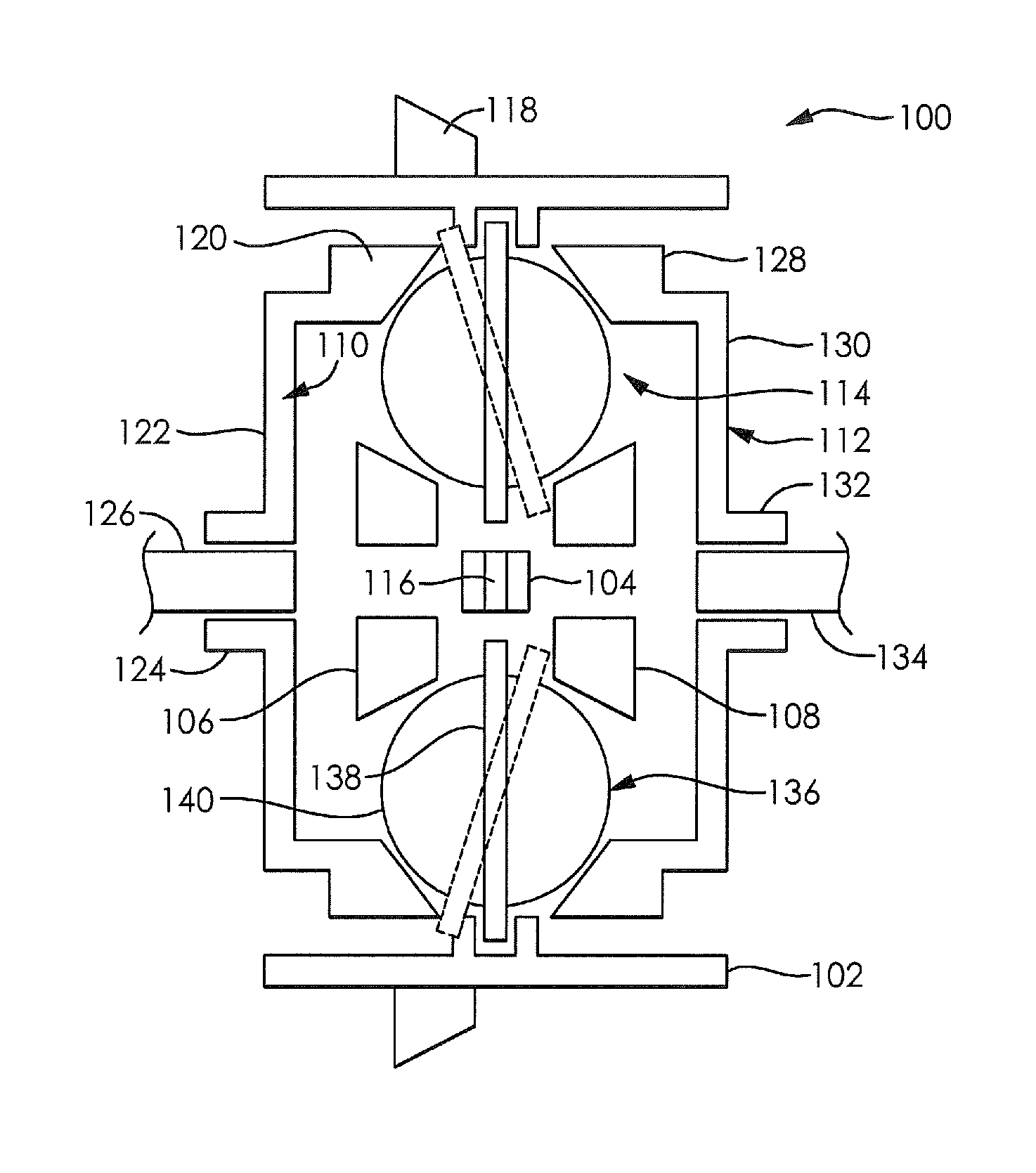
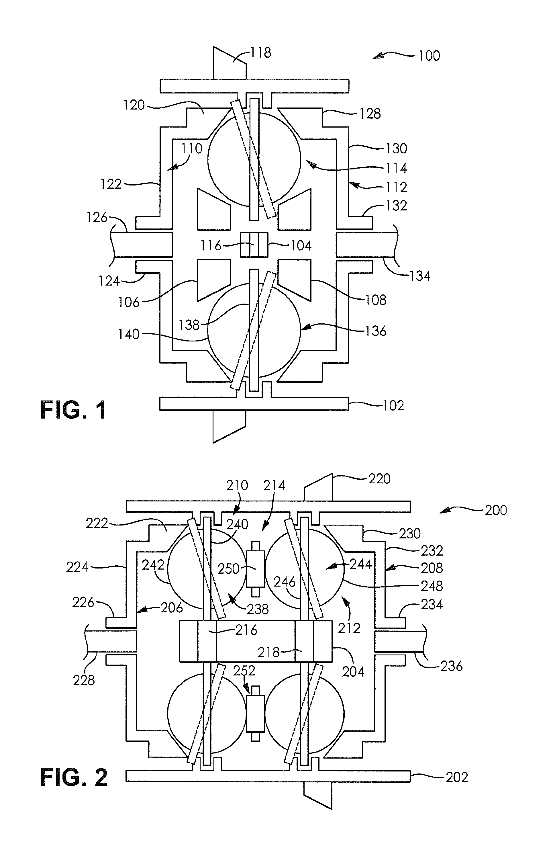
[0021]FIG. 1 illustrates a torque vectoring device 100. The torque vectoring device 100 comprises an outer cage 102, an inner cage 104, a first idling ring 106, a second idling ring 108, a first output ring 110, a second output ring 112, and a plurality of variator ball assemblies 114. The first idling ring 106, the second idling ring 106, the first output ring 110, and the second output ring 112 are rotatably disposed wit...


PUM


Abstract

A torque vectoring device is provided. The torque vectoring device includes a drive member engaged with a power source, a plurality of spherical adjusters configured to be tiltable and rotatable with respect to the drive member, a first output frictionally engaged with the spherical adjusters, and a second output frictionally engaged with the spherical adjusters. A torque distribution between the first output and the second output may be adjusted by tilting the plurality of spherical adjusters. The spherical adjusters also facilitate a differential action between the first output and the second output.

Description

CLAIM OF PRIORITY[0001]The present application claims priority to and incorporates by reference U.S. Provisional Application No. 61 / 598,973 filed Feb. 15, 2012, entitled “TILTING BALL VARIATOR CONTINUOUSLY VARIABLE TRANSMISSION TORQUE VECTORING DEVICE” and U.S. Provisional Application No. 61 / 588,272 filed Jan. 19, 2012, entitled “TILTING BALL VARIATOR TORQUE VECTORING DEVICE.”BACKGROUND OF THE INVENTION[0002]Vehicles including a torque vectoring device have many advantages over vehicles not including torque vectoring devices. In addition to performing a differential function between wheels or axles of a vehicle, the torque vectoring device may be configured to vary torque between wheels or axles of a vehicle at the request of a control system of the vehicle or by an operator of the vehicle.[0003]Conventionally, torque vectoring devices disposed between wheels of a vehicle may include a pair of clutches which may be individually engaged in response to a detected “slip” condition. Eng...

Claims


Application Information

Patent Timeline
Patent Type & Authority Applications(United States)
IPC IPC(8): F16H15/40
CPCF16H15/40B60K17/20B60K23/04F16H15/52B60K2023/043F16H2048/362F16H15/28F16H48/12F16H48/06
Inventor VERSTEYHE, MARK R.J.DUCHENE, THIBAUT E.BYLTIAUW, MATTHIAS W.J.
Owner DANA CORP
Why Eureka
Try Eureka