
Buttress Support Design For EEA Anvil

a support and eea anvil technology, applied in the field of surgical instruments, can solve problems such as bleeding, anastomotic leakage, and tissue tear during stapler extraction, and achieve the effects of avoiding bleeding, avoiding bleeding, and avoiding bleeding

Active Publication Date: 2013-08-01
TYCO HEALTHCARE GRP LP
View PDF7 Cites 252 Cited by
  • Summary
  • Abstract
  • Description
  • Claims
  • Application Information

AI Technical Summary

Benefits of technology

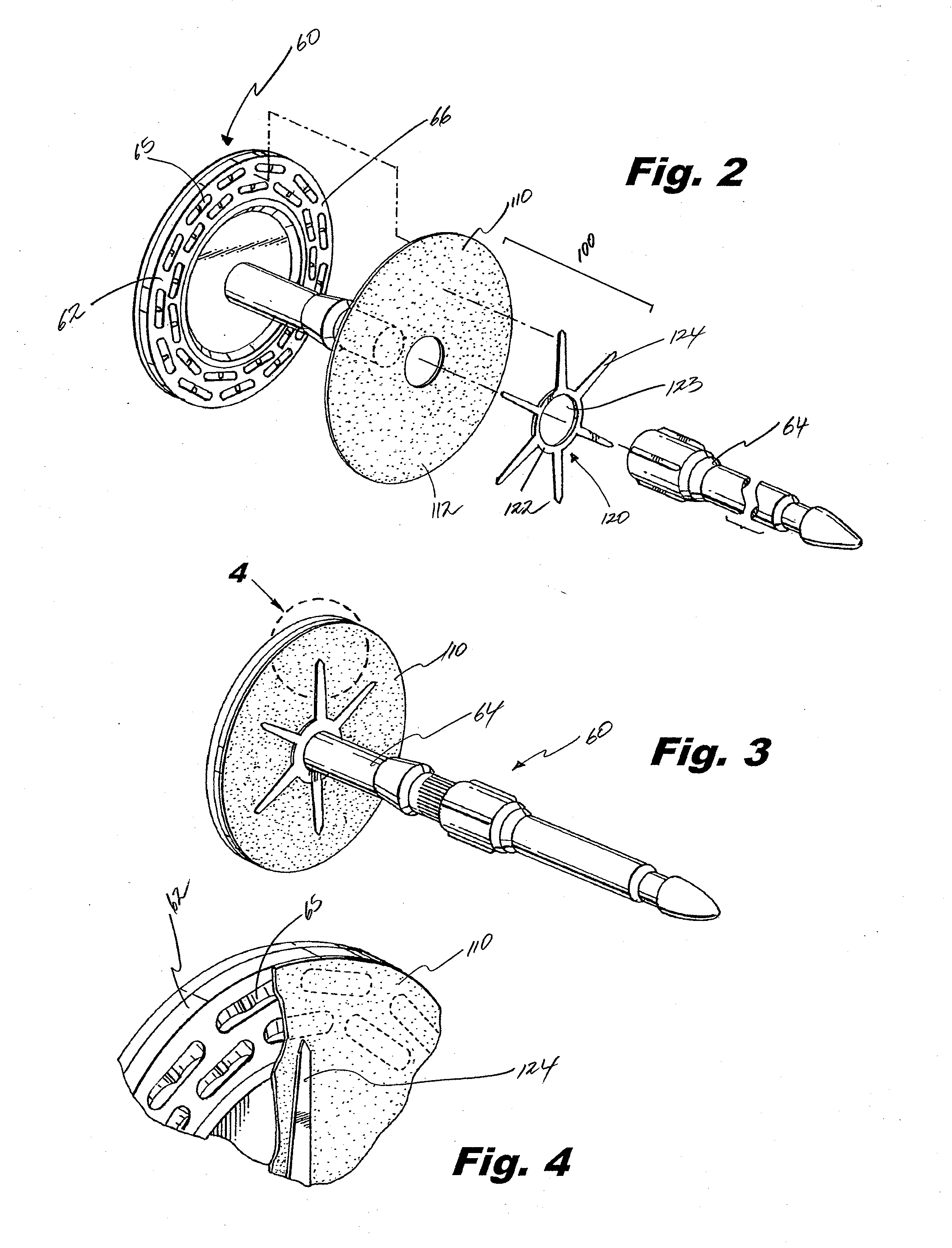
The present invention provides an apparatus for joining two hollow organ sections with a annular array of surgical staples. The apparatus includes a staple cartridge component, an anvil component, a knife member, a buttress member, and a buttress mount. The buttress mount is detachably secured with the anvil component and includes a core ring, an outer ring, and at least one spoke extending between the core ring and the outer ring. The buttress mount at least partially underlying the buttress member provides support thereto. The apparatus also includes a handle assembly, an elongate tubular member, and a knife member. The buttress member is concentric with the plurality of staple pockets defined in the anvil component and can be detachably secured to the anvil member. The buttress mount includes a support member that engages the buttress member to securely hold it in place during use. The apparatus provides a secure and effective method for joining hollow organ sections with a surgical staple cartridge.

Problems solved by technology

While circular staplers are helpful in a number of surgical procedures, problems such as anastomotic leak, tearing of tissue during stapler extraction, bleeding, and other complications may arise.
However, due to the inherent difficulty in positioning and securing such materials with the instrument, a need exists for the buttress material that can be safely and effectively positioned with the anvil.

Method used


Image

  • Buttress Support Design For EEA Anvil
  • Buttress Support Design For EEA Anvil
  • Buttress Support Design For EEA Anvil

Examples


Embodiment Construction

[0033]Embodiments of the present disclosure will now be described in detail with reference to the drawings, in which like reference numerals designate identical or corresponding elements in each of the several views. As used herein, the term “distal,” as is conventional, will refer to that portion of the instrument, apparatus, device or component thereof which is farther from the user while, the term “proximal,” will refer to that portion of the instrument, apparatus, device or component thereof which is closer to the user. In the following description, well-known functions or constructions are not described in detail to avoid obscuring the present disclosure in unnecessary detail.

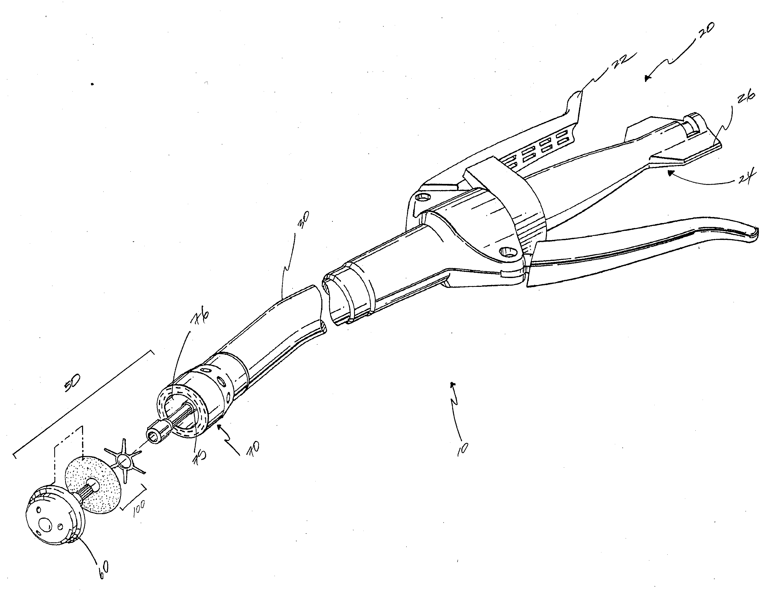
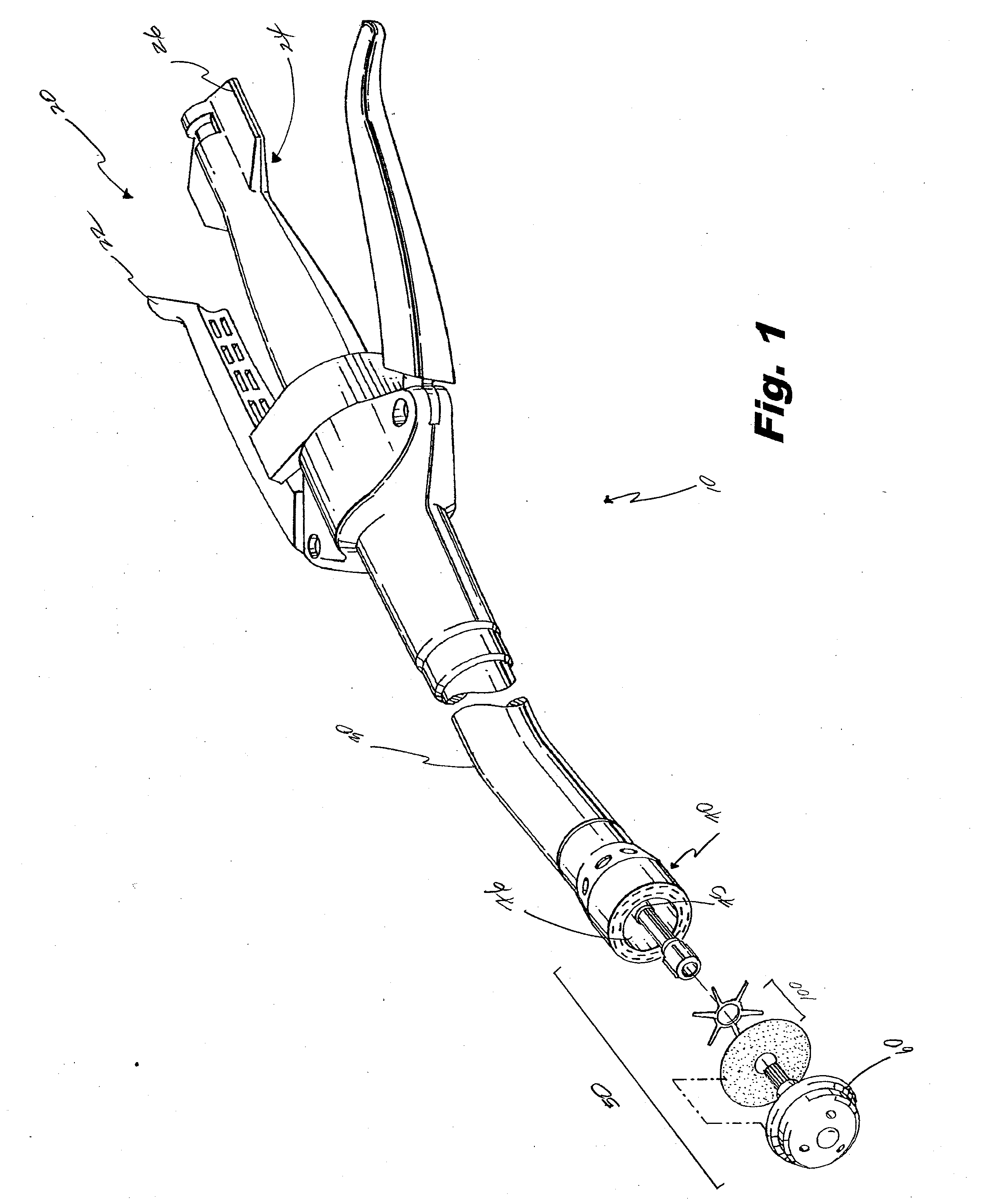
[0034]With reference to FIG. 1, a surgical stapling apparatus 10 for performing circular anastomosis of hollow organs is shown. Surgical stapling apparatus 10 drives a circular array of staples 7 (FIG. 15) through the end sections of each organ and simultaneously fires an annular knife 76 (FIG. 15) to seve...


PUM

PropertyMeasurementUnit
thicknessaaaaaaaaaa
areaaaaaaaaaaa
strengthaaaaaaaaaa

Abstract

An apparatus for joining two hollow organ sections with an annular array of surgical staples includes a staple cartridge, an anvil, a buttress member, and a buttress mount. In particular, the staple cartridge includes a plurality of surgical staples in an annular array. The anvil includes an anvil member and a shaft extending therefrom. The anvil member defines a plurality of staple pockets for deforming the surgical staples. The anvil is movable relative to the staple cartridge component between spaced apart and approximated positions to adjustably clamp tissue between the staple cartridge and the anvil. The buttress member is concentrically aligned with the plurality of staple pockets defined in the anvil member. The buttress mount is detachably secured with the shaft of the anvil. The buttress mount includes at least one support member radially extending outward to secure the buttress member to the anvil member.

Description

BACKGROUND[0001]1. Technical Field[0002]The present disclosure relates to a surgical instrument for applying surgical fasteners or staples to body tissue, and more particularly, to a surgical buttress assembly for use with an end-to-end anastomosis stapling apparatus.[0003]2. Background of Related Art[0004]Anastomosis is a surgical joining of separate hollow organ sections. Typically, an anastomosis procedure follows surgery in which a diseased or defective section of hollow tissue is removed and the remaining end sections are joined. Depending on the desired anastomosis procedure, the end sections may be joined by either circular, end-to-end or side-to-side organ reconstruction methods.[0005]In a circular anastomosis procedure, the two ends of the organ sections are joined by means of a stapling instrument which drives a circular array of staples through the end section of each organ section and simultaneously cores any tissue interior of the driven circular array of staples to fre...

Claims


Application Information

Patent Timeline
Patent Type & Authority Applications(United States)
IPC IPC(8): A61B17/115
CPCA61B17/1155A61B17/07292A61B2017/07214A61B2017/07257A61B2017/1132
Inventor STEVENSON, RICHARD P.CASASANTA, JR., THOMASCARTER, SALLY
Owner TYCO HEALTHCARE GRP LP
Learn More