Device for attaching a tablet computer

a tablet computer and tablet technology, applied in the field of tablets for attaching, can solve the problems of unfavorable interactive use of the screen or tablet computer in the passive mode of viewing, and achieve the effect of simple and rapid fashion

Active Publication Date: 2013-08-08
KINETIX
View PDF15 Cites 31 Cited by
  • Summary
  • Abstract
  • Description
  • Claims
  • Application Information

AI Technical Summary

Benefits of technology

[0050]In a preferred embodiment, a fastening device is provided for mounting the device to the columns of a head rest. This enables later installation into almost any vehicle without requiring any structural provisions on the part of the vehicle manufacturer.
[0051]The devic

Problems solved by technology

The position of use of the screen or tablet computer in the passive mode of viewing is, however

Method used


Image

  • Device for attaching a tablet computer
  • Device for attaching a tablet computer
  • Device for attaching a tablet computer

Examples


first embodiment

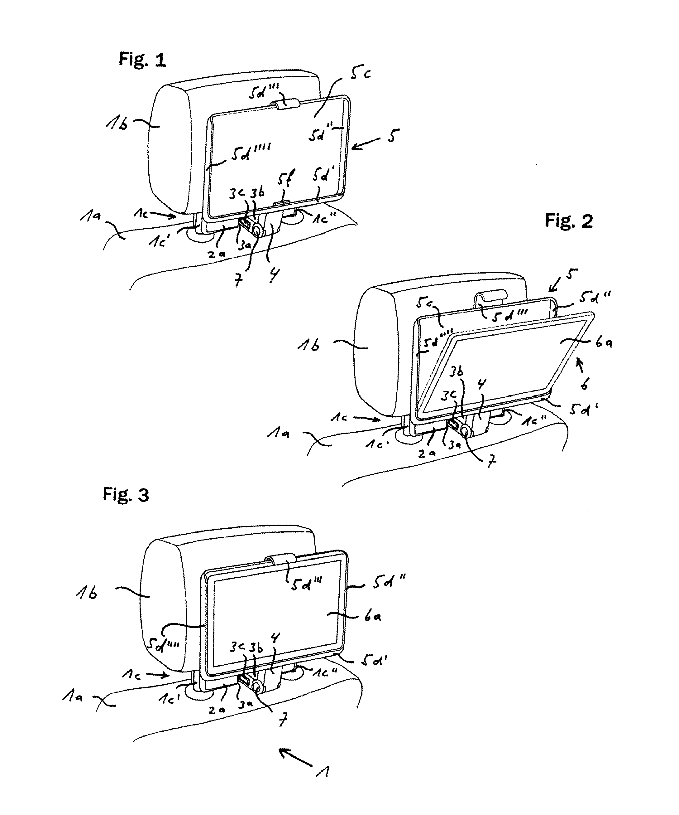
[0114]FIGS. 1 through 6 show a first variant of the device with the transfer configuration. The height-adjustable head rest 1b with head rest columns 1c′, 1c″ is mounted to the back rest 1a of the vehicle seat 1. A spring-loaded clamping element 2a is inserted between the head rest columns 1c′, 1c″. A locating bushing 3a is arranged in the center of the clamping element 2a, into which a connector element 3b is inserted and locked in the locating bushing 3a by a locking device 3c that can be released via lateral buttons.

[0115]A first joint 7 is arranged at the rear end of the connector element 3b, to which joint one end of a carrier element 4 is hinged. At the other end of the carrier element 4, a rear wall 5c of a holder 5 is connected via a second joint 8 to the carrier element 4. The axes of the first joint 7 and the second joint 8 extend parallel to the rear broad side of the back rest la or the head rest 1b.

[0116]A pivot joint 5a is arranged between the second joint 8 and the r...

second embodiment

[0121]FIG. 7 shows the inventive device with the transfer configuration, in which the carrier element 4 comprises a carriage 4a connected to the first joint 7, which forms a linear guidance together with a guide rail 5g arranged on the holder 5, the linear guidance displacing the holder 5 relative to the first joint 7. The first view shows the holder 5 in the first position of use. The center view shows an intermediate position of the holder 5 and the last view shows the holder 5 in the second position of use.

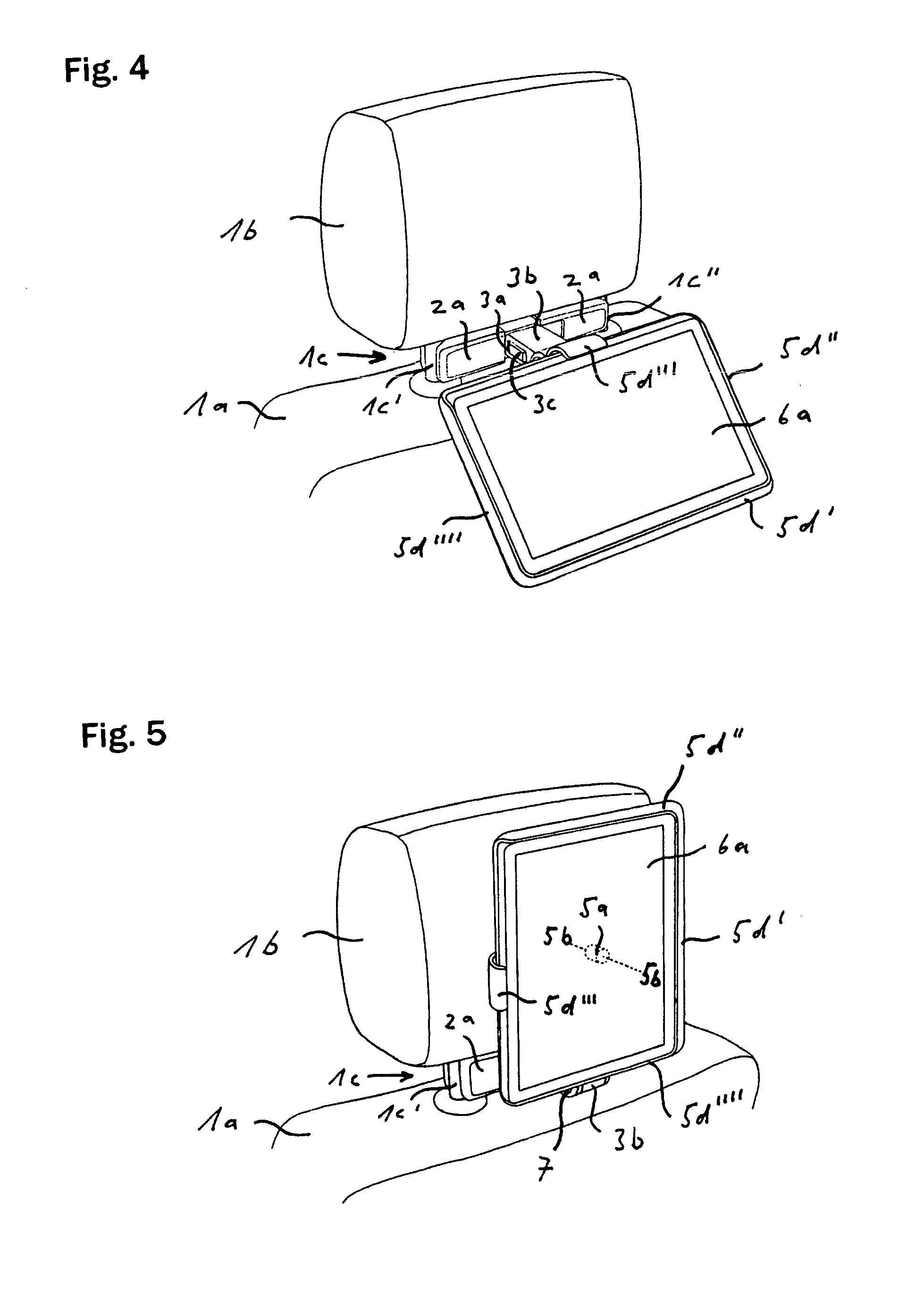
[0122]The first joint 7 is also designed as a friction hinge in this second variant such that the respective setting of the holder is maintained. A pivot joint 5a is also arranged between the carrier element 4 and the rear wall 5c of the holder 5, the axis of rotation 5b of which extends perpendicularly to the broad side of the rear wall 5c (FIG. 5).

[0123]FIGS. 8 through 16 show detailed views of the second variant of the inventive device in accordance with FIG. 7. The joint be...

third embodiment

[0135]FIGS. 17 to 19 show a third variant of the device with the transfer configuration. The carrier element 40′ is connected via a lower joint 71, 71′ to the connector element 30b′ and via an upper joint 40c′, 50k′ to the holder 50′, wherein the axes of rotation 5b, 5b′ of the two joints 71, 71′, 40c′, 50k′ extend perpendicularly to the rear wall 50a′ of the holder 50′ and parallel to each other. The movement of the holder 50′ between the first and the second position of use is therefore performed in one plane, the inclination of which is realized through pivoting the carrier element 40′ about the first joint 70′.

[0136]In the first position of use of the holder 50′, the longitudinal axis of the carrier element 40′ extends from the lower joint 71, 71′ in a vertical upward direction and the upper joint 40c′, 50k′ is located perpendicularly above the lower joint 71, 71′ (FIG. 18).

[0137]In the second position of use (dashed lines) of the holder 50′, the longitudinal axis of the carrier...


PUM


Abstract

A device for attaching a tablet computer to the rear-side of a vehicle seat part has a carrier element (4, 10, 40′, 40″, 140) which is displaceably connected to a fastening device (2, 2a, 3a, 3b, 3c, 20, 20a, 30b, 30′, 130b, 30c, 130c) and to which a support (5, 50, 50′, 50″) is displaceably connected for receiving the tablet computer (6, 60). The support (5, 50, 50′, 50″, 59, 150) can be moved between a first user position in which the screen (6a, 60a, 60a′, 60a″) of the tablet computer (6, 60) is arranged on the side opposite the vehicle seat part (1a, 1b, 1c, 1c′, 1c″, 10a, 10a′, 10b, 10c) and aligned essentially vertically and a second user position in which the screen (6a, 60a, 60a′, 60a″) is oriented upward and essentially horizontally or oblique to the user.

Description

[0001]This application is the national stage of PCT / EP2011 / 000393 filed Jan. 28, 2011 and also claims Paris convention priority of DE 10 2010 006 261.8 filed Jan. 28, 2010, DE 10 2010 020 082.4 filed May 10, 2010, DE 10 2010 021 372.1 filed May 25, 2010, DE 10 2010 024 095.8 filed Jun. 17, 2010 and DE 20 2010 026 941.7 filed Jul. 12, 2010 the entire disclosures of which are hereby incorporated by reference.BACKGROUND OF THE INVENTION[0002]The invention concerns a device for attaching a tablet computer, in particular, to the rear side of a motor vehicle seat part such as a back rest, head rest or head rest mounting of a vehicle seat.[0003]In contrast to a notebook computer comprising a keypad and a screen block, which are connected via a joint, a tablet computer consists of one single block with integrated flat screen, on which the entries are made via automatically displayed keyboards or with an electronic stylus. The length and width of the block approximately correspond to the dim...

Claims


Application Information

Patent Timeline
IPC IPC(8): B60R7/04
CPCB60R11/0235B60R11/0252B60R7/04B60R2011/0087B60R2011/0017
Inventor ACKERET, PETERSKOTT, JUERGEN SIEGFRIED
Owner KINETIX
Why Eureka
Try Eureka