Method and system for filling in a parallelogram

a parallelogram and filling technology, applied in the field of filling in parallelograms, can solve the problems of complex representation, high memory space cost, and inability to use very practicality,

Inactive Publication Date: 2006-10-05
KONINKLIJKE PHILIPS ELECTRONICS NV
View PDF2 Cites 4 Cited by
  • Summary
  • Abstract
  • Description
  • Claims
  • Application Information

AI Technical Summary

Benefits of technology

[0024] A major advantage of the second embodiment is to provide an exhaustive filling in of the parallelogram, that is to say without any hole. Translating a se

Problems solved by technology

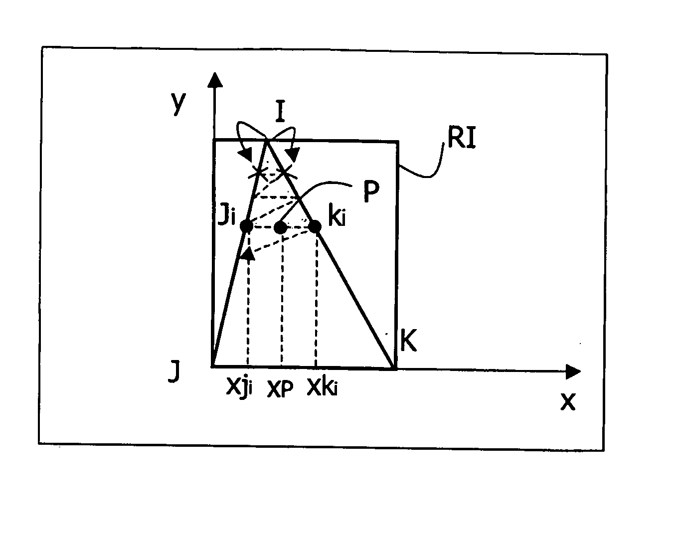
In the field of video games and more generally the synthesis of images, the problem is posed of displaying objects of interest with more or less complex shapes on a graphical screen comprising a discrete grid of points, commonly referred to as pixels in a two-dimensional space and voxels in a three-dimensional space.
One

Method used


Image

  • Method and system for filling in a parallelogram
  • Method and system for filling in a parallelogram
  • Method and system for filling in a parallelogram

Examples


first embodiment

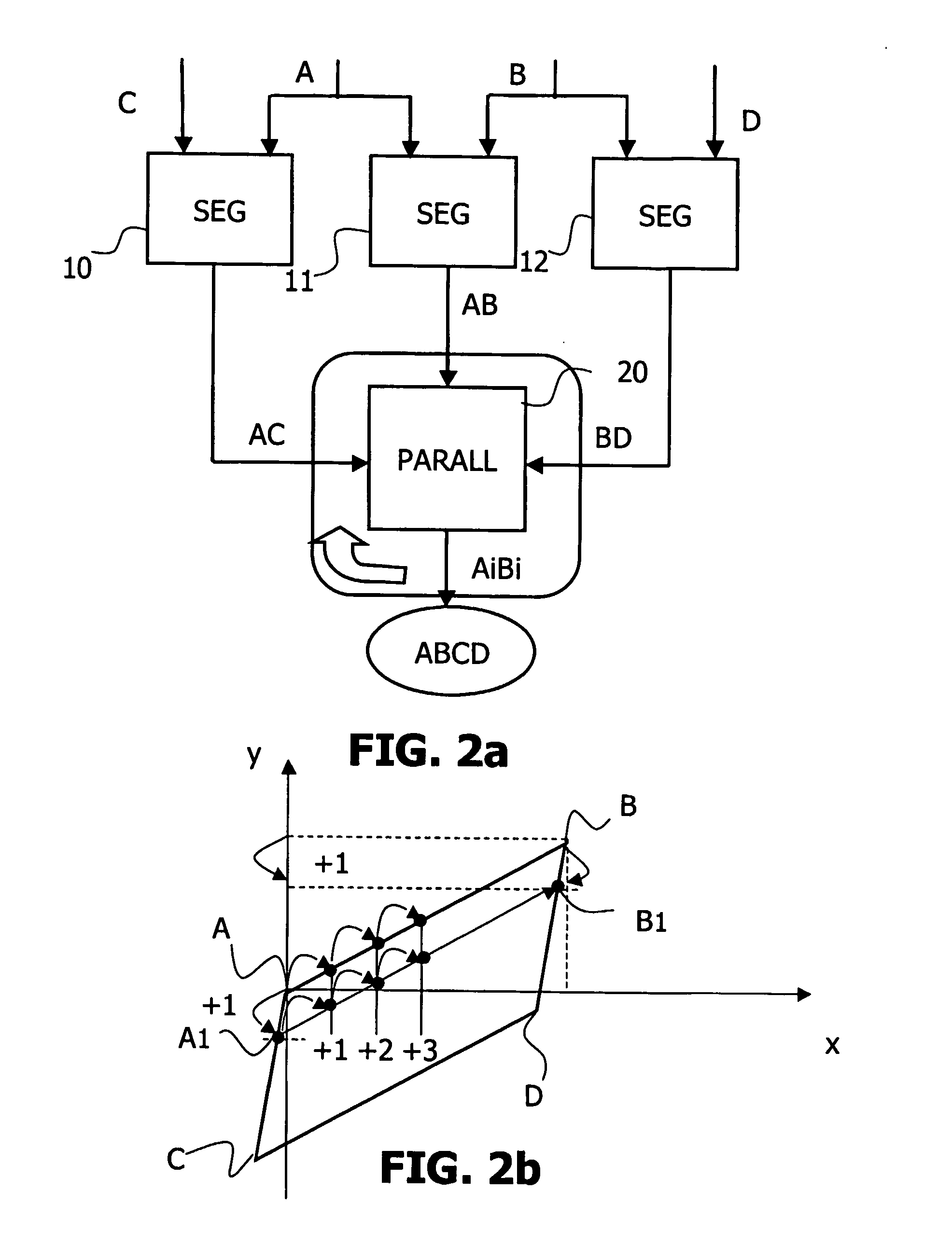
[0051] In the invention, described by the functional diagram in FIG. 4 and illustrated by the example in FIG. 2b, said step 20 comprises a substep 21 of calculating the coordinates of a segment included between a point Ai belonging to the second segment AC and a point Bi belonging to the third segment BD, Ai and Bi being situated at the same distance from A and B respectively. The substep 21 is iterated in order to trace all the segments AiBi situated within the parallelogram ABCD and at equal distances from A and B respectively in a horizontal or vertical favored direction. In the example in FIG. 2b, the favored direction of the segments AC and BD is the vertical axis Ay. Starting from xA, the point A1 of the second segment AC is considered, such that yA1=yA+1 and the corresponding point B1 of the third segment BD, such that yB1=yB+1. The second and third segments AC and BD being parallel, the points A1 and B1 are at equal distances from A and B respectively along the axis Ay.

[0052...

second embodiment

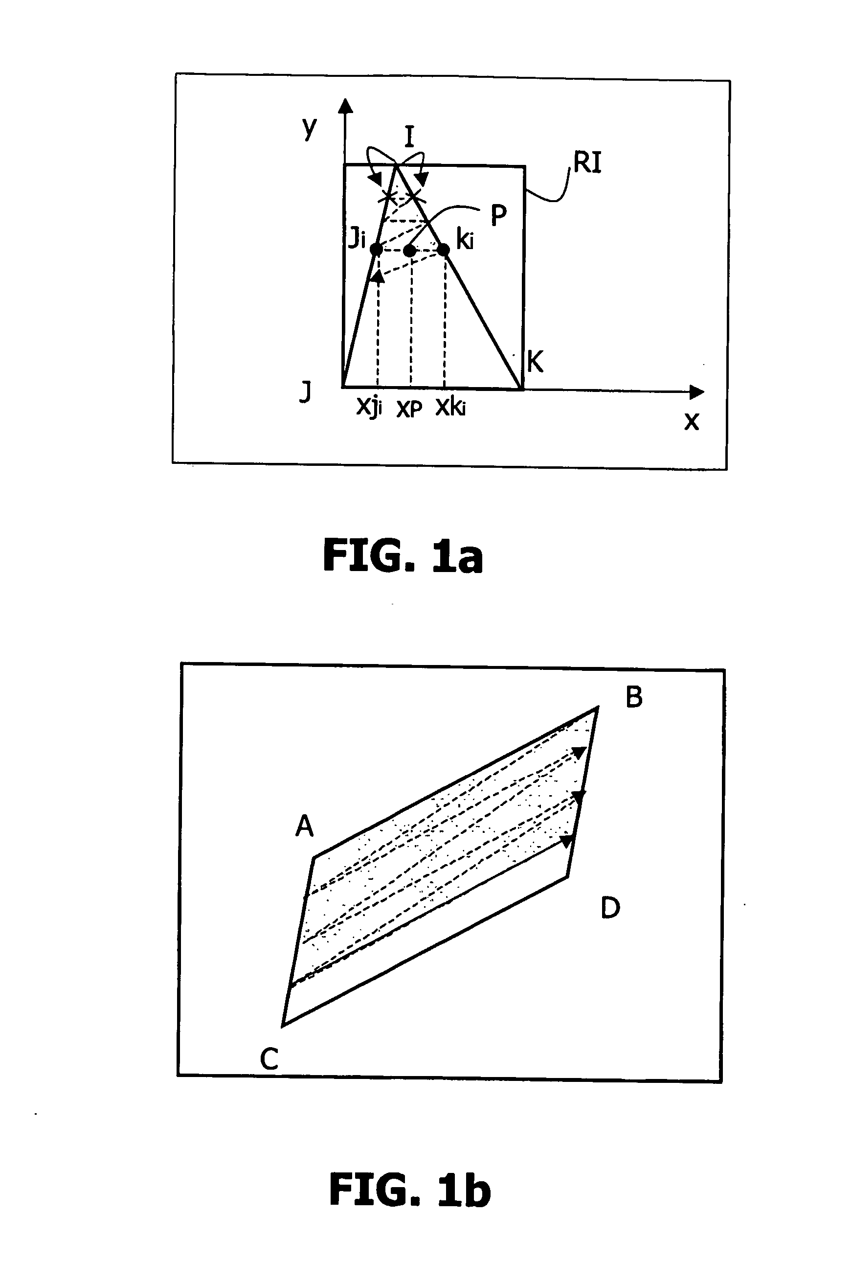
[0056] In the invention, presented functionally in FIG. 6, step 20 comprises a substep 22 of translation of the first segment AB in a horizontal and vertical favored direction, intended to supply a translated segment included in the parallelogram ABCD. This translation subset 22 consists of calculating the coordinates of a segment parallel to the first segment AB by translation in a horizontal or vertical favored direction. FIG. 7a presents an example of horizontal translations of the segment AB along the axis Ax inside the parallelogram ABCD. Such translations are very simple to implement. Consider in fact a segment A′1B′1 translated horizontally by one unit in the direction of the positive x's. This gives simply xA′1=xA+1 and yA′1=yA. In this way, all the possible translated segments A′iB′i, such as xAA′≦xC are traced. A parallelogram 6 is formed. Only the points belonging to a surface 5 common to the parallelogram 6 with the parallelogram ABCD must be taken into account. To do th...


PUM


Abstract

The invention relates to a method of tracing and filling in a parallelogram (ABCD), comprising a first vertex (A), a second vertex (B), a third vertex (C) and a fourth vertex (D) on a discrete grid of a graphics screen from knowledge of the coordinates of its vertices. The method according to the invention comprises a step (10) of calculating the coordinates of the points on a first segment (AB) between the first vertex (A) and the second vertex (B), a step (11) of calculating the coordinates of the points on a second segment (AC) between the first vertex (A) and the third vertex (C), a step (12) of calculating the coordinates of the points on a third segment (BD) between the second vertex (BD) and the fourth vertex D and an iterative step (20) of calculating the coordinates of the points on a segment parallel to the segment AB and included within the parallelogram ABCD. Advantageously, the steps of calculating coordinates of the points on a segment use a so-called mid-point algorithm or Bresenham's algorithm.

Description

FIELD OF THE INVENTION [0001] The present invention relates to a method of filling in a parallelogram. It also relates to a system implementing such a method. Finally, it relates to a computer program implementing such a method. [0002] It finds its application in particular in the fields of image synthesis, video games in two or three dimensions and the processing of video objects according to the MPEG-4 standard. BACKGROUND OF THE INVENTION [0003] In the field of video games and more generally the synthesis of images, the problem is posed of displaying objects of interest with more or less complex shapes on a graphical screen comprising a discrete grid of points, commonly referred to as pixels in a two-dimensional space and voxels in a three-dimensional space. For this purpose, the objects of interest are decomposed into primary forms, generally triangles, which are traced and filled in on the discrete grid on the screen from knowledge of the coordinates of their vertices, allocati...

Claims


Application Information

Patent Timeline
IPC IPC(8): G06T11/20G06T11/40
CPCG06T11/40
Inventor ZHAO, QINPASQUIER, LAURENTDURANTON, MARC
Owner KONINKLIJKE PHILIPS ELECTRONICS NV
Why Eureka
Try Eureka