Incomplete fitting prevention connector

a technology of inconvenient fitting and connector, which is applied in the direction of incorrect coupling prevention, coupling device connection, electrical apparatus, etc., and can solve the problem of greater insertion for

Active Publication Date: 2013-08-15
YAZAKI CORP
View PDF8 Cites 19 Cited by
  • Summary
  • Abstract
  • Description
  • Claims
  • Application Information

AI Technical Summary

Benefits of technology

[0010]The present invention has been made to solve the above-described matters and an object of the present invention is to provide an incomplete fitting prevention connector which is capable of preventing increase in the insertion force even when a connector including a CPA and a packing further includes a short spring and also preventing the increase in the insertion force even when a terminal is a number of the terminal is plural number.
[0011](1) According to an aspect of the invention, an incomplete fitting prevention connector includes a first connector, a second connector that is fitted to the first connector, and a connector position assurance lock (CPA) that is slidably mounted to an outer side of the second connector. The first connector includes a male beak, a short spring and a terminal. The second connector includes a female lock passing over the male beak and a short-circuit removal plate part inserted between the short spring and the terminal. A draw-in slanted surface is formed at a leading end of the male beak, a restoring force for returning the female lock to its original position serves as a driving force for fitting the connector when the female lock reaches the draw-in slanted surface, and the insertion force of the short-circuit removal plate part applied between the short spring and the terminal is reduced.
[0014]According to the incomplete fitting prevention connector having a configuration of the above (2), it is possible to secure one-action property by using the restoring force for returning the CPA lock to its original position as the driving force when the CPA lock reaches the leading-end slanted surface.

Problems solved by technology

However, in a case where a configuration including a short spring is additionally provided to the connector, there was a matter that the insertion force becomes greater when inserting a short-circuit removal plate part to the short spring.

Method used


Image

  • Incomplete fitting prevention connector
  • Incomplete fitting prevention connector
  • Incomplete fitting prevention connector

Examples


Embodiment Construction

[0025]Hereinafter, with reference to the drawings, an incomplete fitting prevention connector according to an exemplary embodiment of the present invention will be described which is capable of preventing increase in the insertion force and satisfying an incomplete fitting prevention function, even when the connector includes a short spring and further even when a number of the terminal is plural number.

[0026]

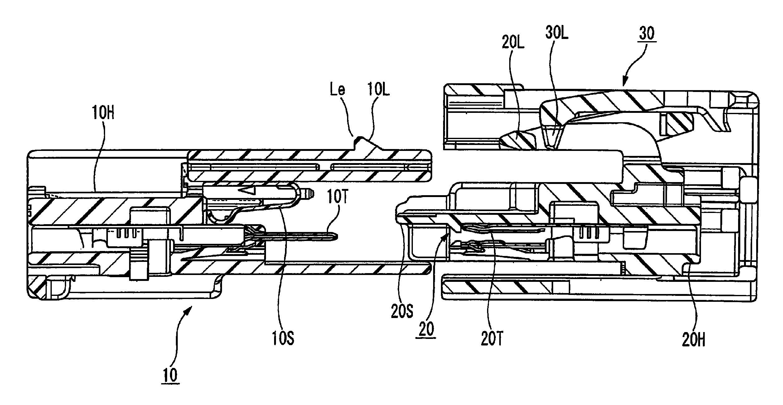
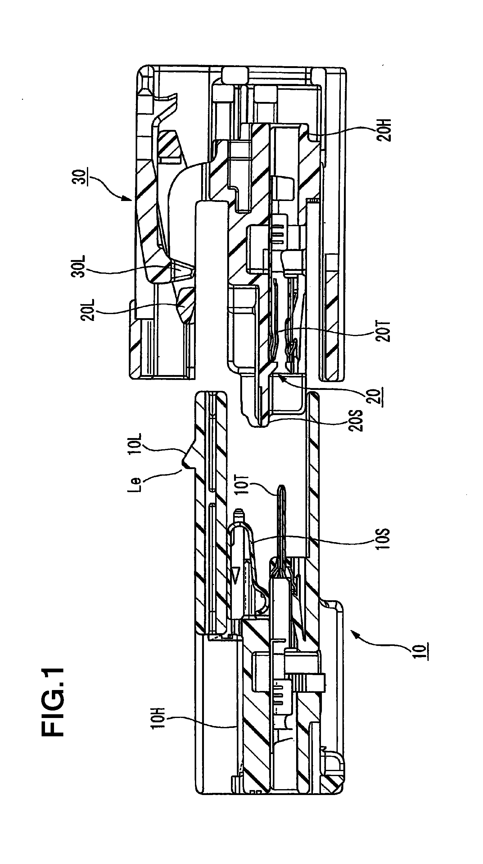
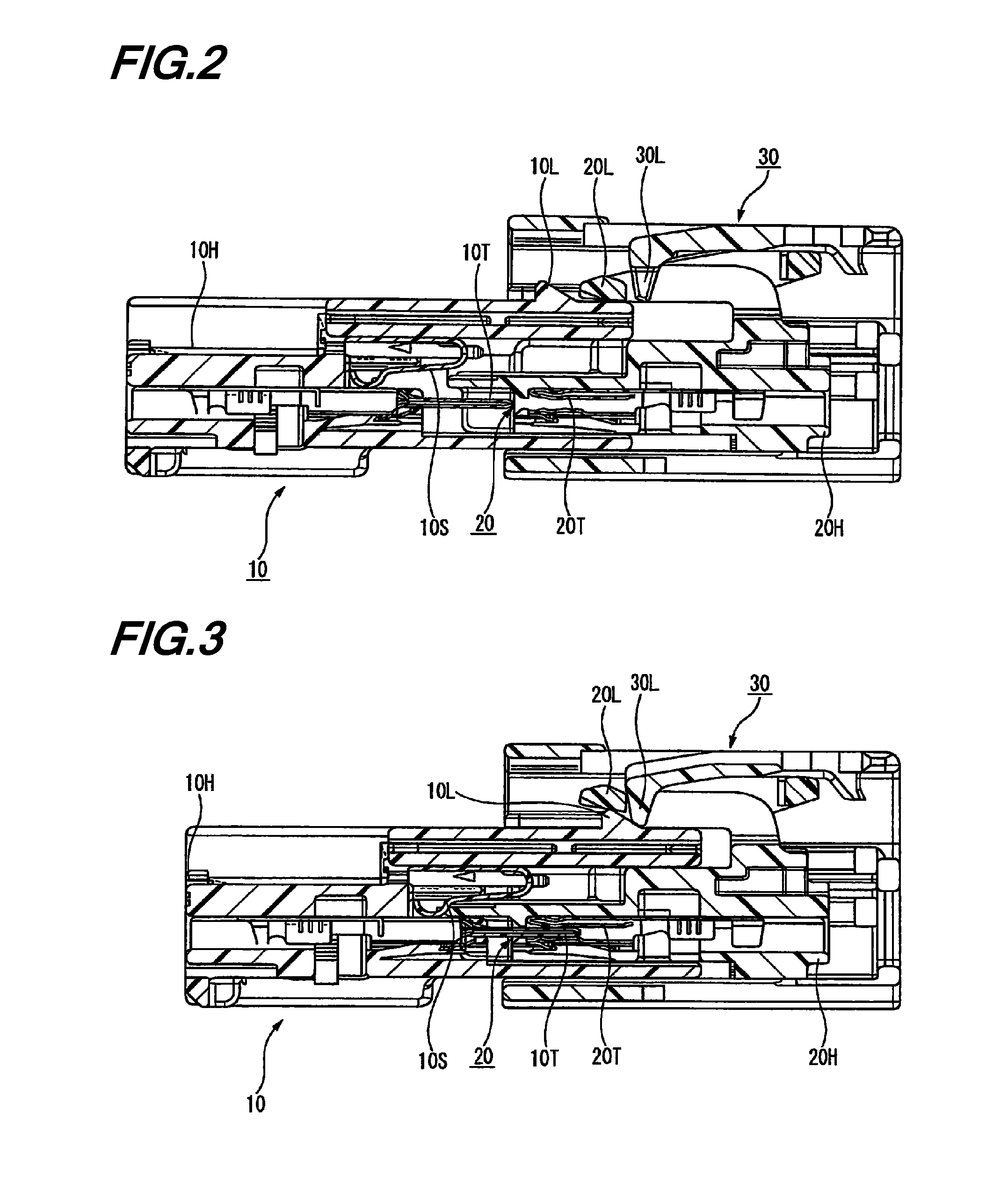
[0027]FIG. 1 is a longitudinal sectional view showing a male connector and a female connector according to an exemplary embodiment of the present invention before fitting. An incomplete fitting prevention connector according to the present embodiment mainly includes a first connector (for example, a male connector) 10, a second connector (for example, a female connector) 20 fitted to the first connector and a connector position assurance lock (hereinafter, referred to as a “CPA”) 30 slidably mounted to an outer side of the male connector 20.

[0028]Hereinafter, the male connector...


PUM


Abstract

An incomplete fitting prevention connector includes a first connector, a second connector that is fitted to the first connector, and a connector position assurance lock that is slidably mounted to an outer side of the second connector. The first connector includes a male beak, a short spring and a terminal The second connector includes a female lock passing over the male beak and a short-circuit removal plate part inserted between the short spring and the terminal A draw-in slanted surface is formed at a leading end of the male beak, a restoring force for returning the female lock to its original position serves as a driving force for fitting the connector when the female lock reaches the draw-in slanted surface, and the insertion force of the short-circuit removal plate part applied between the short spring and the terminal is reduced.

Description

CROSS REFERENCE TO RELATED APPLICATION[0001]This application is a continuation of PCT application No. PCT / JP2011 / 070621, which was filed on Sep. 9, 2011 based on Japanese Patent Applications No. 2010-208267 filed on Sep. 16, 2010, the contents of which are incorporated herein by reference. Also, all the references cited herein are incorporated as a whole.BACKGROUND OF THE INVENTION[0002]1. Technical Field[0003]The present invention relates to an incomplete fitting prevention connector and, more particularly, to a connector which includes a short spring or a packing and has an incomplete fitting prevention function.[0004]2. Background Art[0005]A connector is known which includes an incomplete fitting prevention function to detect an incomplete fitting state between a male connector housing and a female connector housing (for example, see JP-A-2004-241275).[0006](Object and configuration of the invention disclosed in JP-A-2004-241275) The invention disclosed in JP-A-2004-241275 is int...

Claims


Application Information

Patent Timeline
Patent Type & Authority Applications(United States)
IPC IPC(8): H01R13/642
CPCH01R13/6272H01R13/642H01R13/639H01R13/641H01R13/64
Inventor OSADA, TAKESHITSURUTA, AKIHIROMUKOUJIMA, NOBUYUKI
Owner YAZAKI CORP
Why Eureka
Try Eureka