
Image forming apparatus, controlling method of image forming apparatus, and program

a technology of image forming apparatus and forming apparatus, which is applied in the direction of electrographic process apparatus, visual presentation, instruments, etc., can solve the problems of power-supply switch itself breaking down, the contact of the power-supply switch deteriorating, and the number of times of controlling the mechanical relay being naturally limited

Inactive Publication Date: 2013-08-22
CANON KK
View PDF5 Cites 444 Cited by
  • Summary
  • Abstract
  • Description
  • Claims
  • Application Information

AI Technical Summary

Benefits of technology

The present invention is an image forming apparatus that can operate in multiple power states. It includes a controlling unit that can transition the power state of the apparatus to a first power state, a second power state that can be returned to the first power state, or a third power state in which power is saved compared to the second power state. The apparatus also has a power-supply switch that can be turned off by an internal mechanical relay driven by a manual operation or controlling from the controlling unit. The controlling unit controls to turn off the power-supply switch after transitioning the power state from the second power state to the third power state. This invention allows for more efficient energy usage and better control over power consumption.

Problems solved by technology

However, since the mechanical relay has a lifetime, the number of times of controlling the mechanical relay is naturally limited due to its lifetime.
When the number of times of off / on of the power-supply switch in the frequently performed automatic off driving resultingly exceeds the number of times of off / on defined as the lifetime, there is a possibility that the contact of the power-supply switch deteriorates and thus the power-supply switch itself breaks down.
Therefore, in the usage environment of the user who uses the image forming apparatus frequently, if the automatic off controlling of the power-supply switch is stopped by setting limitation of the number of times of off / on of the power-supply switch when the number of times of off / on of the power switch exceeds the set limitation, a period for which the automatic off controlling can be performed is shortened, whereby there is a possibility that a power-saving effect deteriorates.
Moreover, if the power-supply switch by which the number of times of off / on is ensured according to the user who uses the image forming apparatus frequently is used, costs of the power-supply switch itself increase.
Moreover, in this case, the size of the power-supply switch increases, whereby such an increase of the size of the power-supply switch affects the overall constitution of the image forming apparatus itself.

Method used


Image

  • Image forming apparatus, controlling method of image forming apparatus, and program
  • Image forming apparatus, controlling method of image forming apparatus, and program
  • Image forming apparatus, controlling method of image forming apparatus, and program

Examples


first embodiment

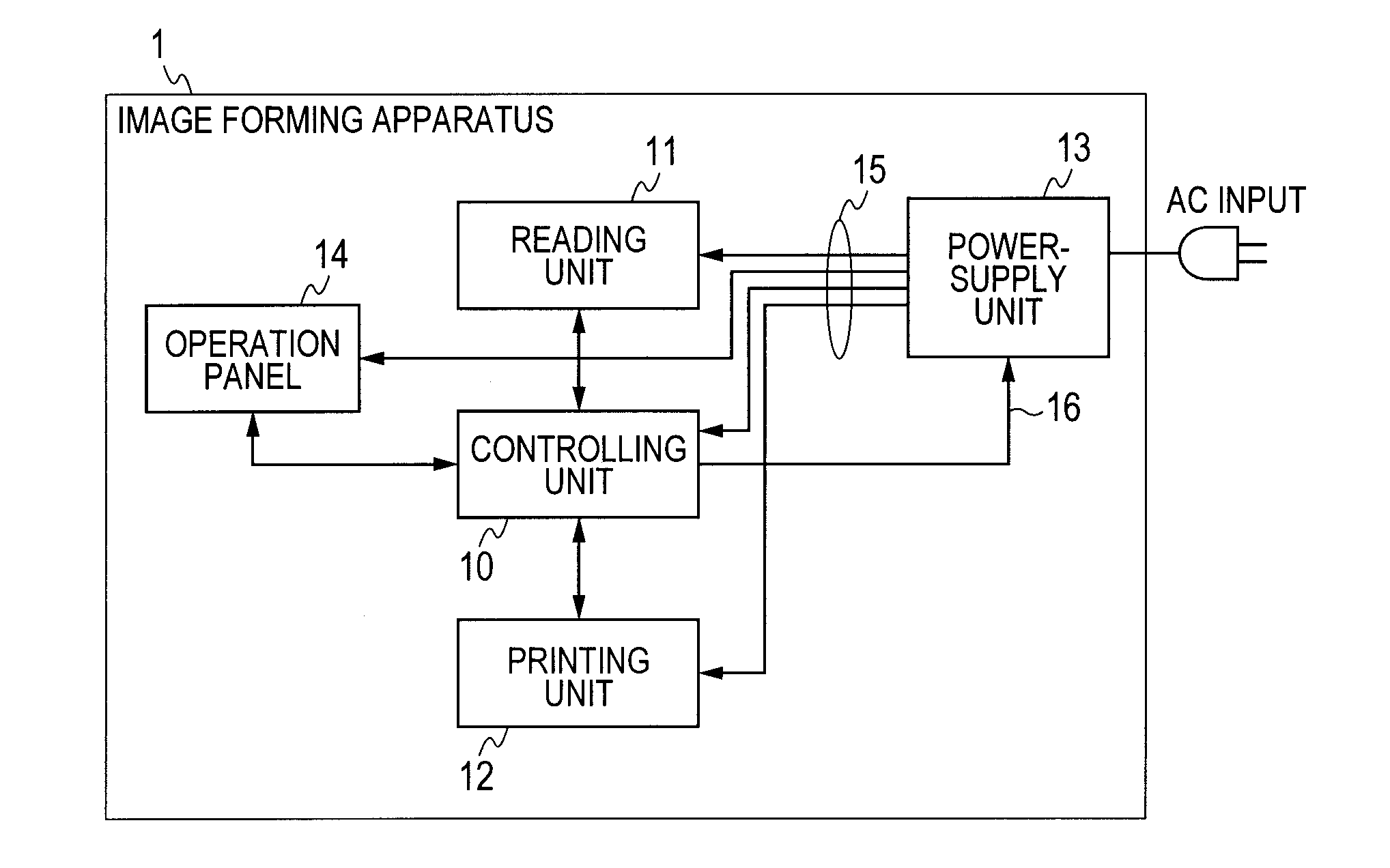
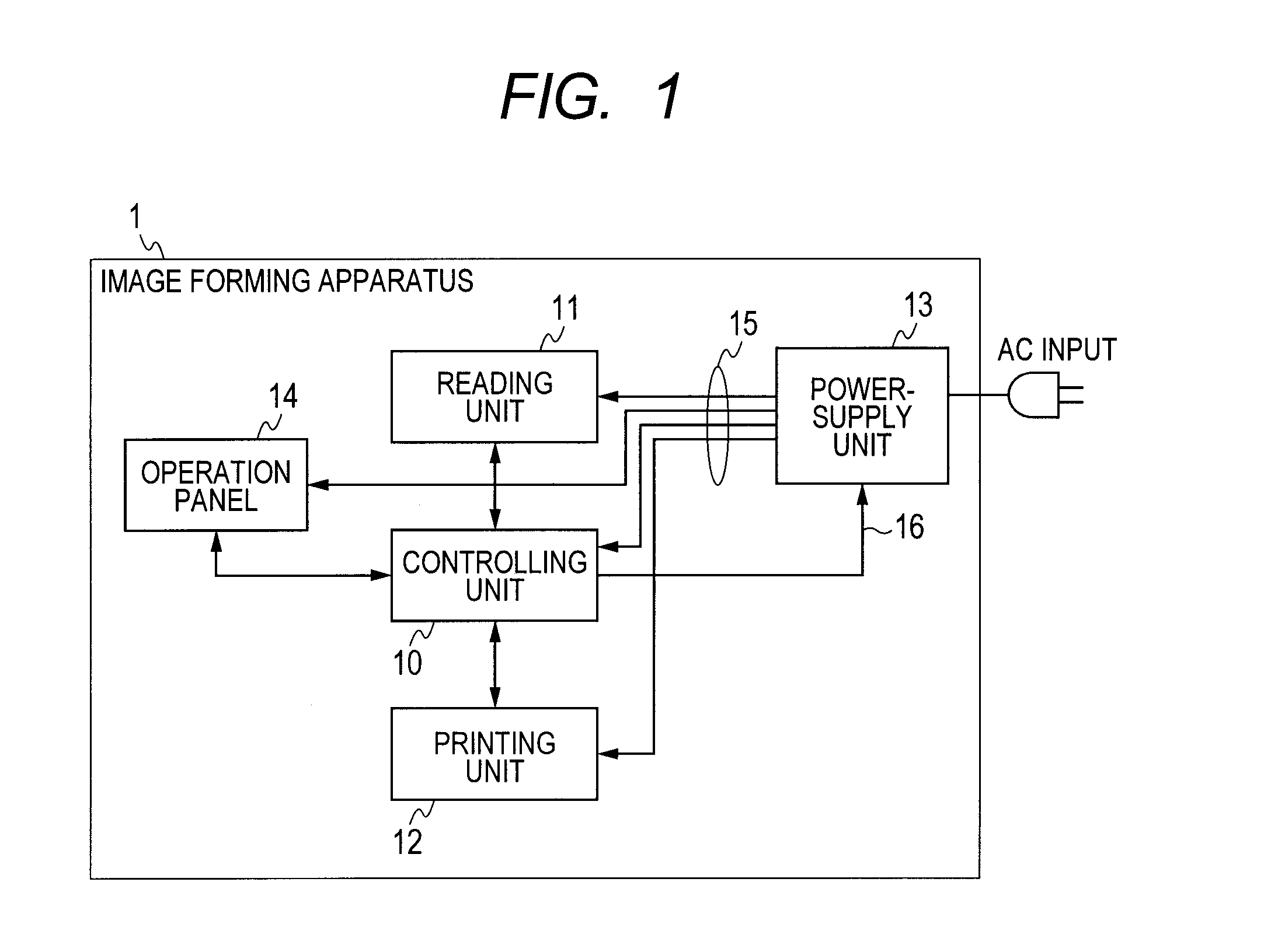
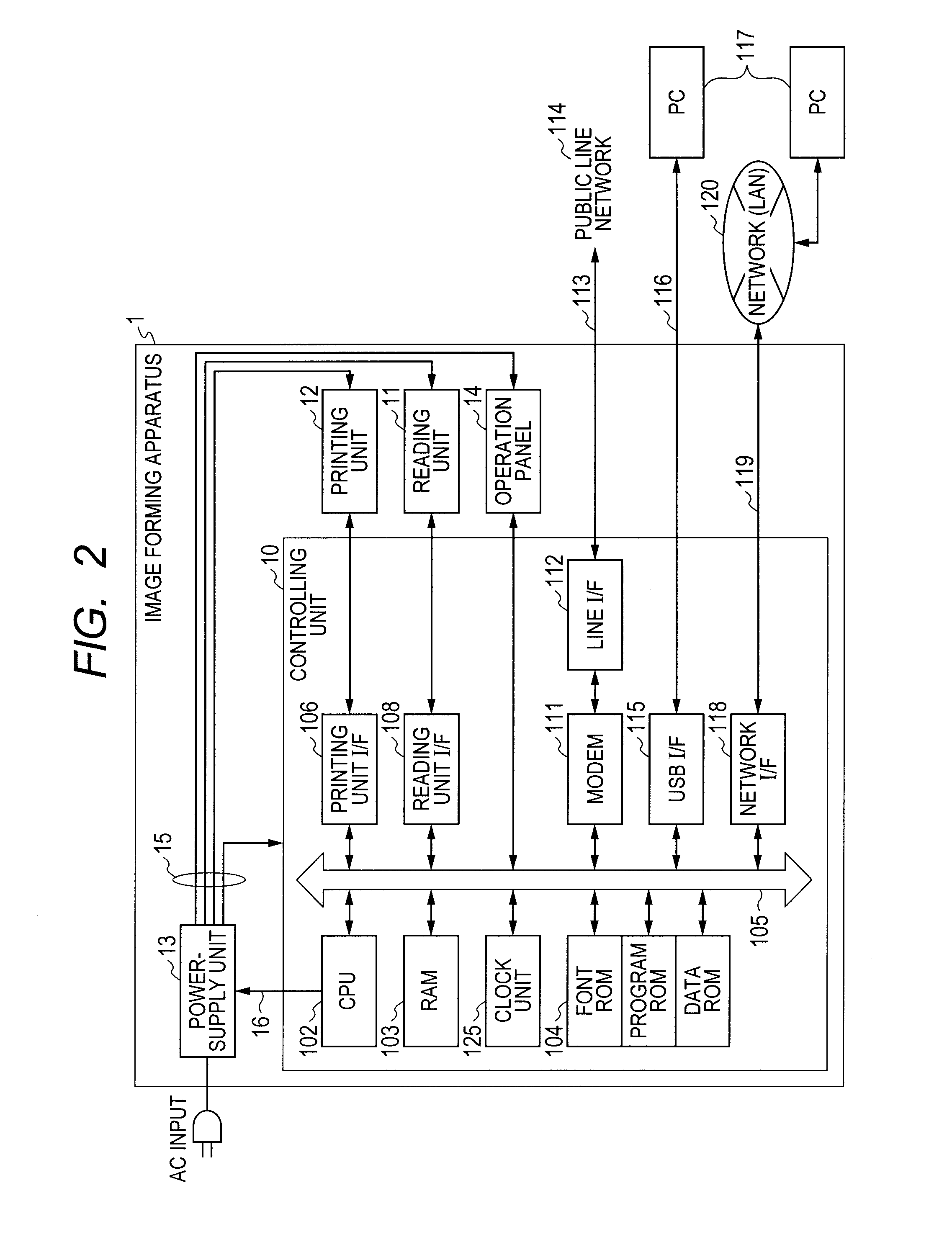
[0024]FIG. 1 is a block diagram illustrating an example of a constitution of an image forming apparatus according to the first embodiment of the present invention. More specifically, FIG. 1 shows an image forming apparatus 1 according to the present embodiment. Here, the image forming apparatus 1 includes a printing unit 12, a reading unit 11, an operation panel 14, a power-supply unit 13, and a controlling unit 10 which controls these units.

[0025]The controlling unit 10 performs various kinds of image processes on the basis of image data received from the reading unit 11, a host computer serving as an external apparatus, a facsimile apparatus connected via a PSTN (public switched telephone network) line (public line), or the like. Then, the controlling unit controls, e.g., the printing unit 12 to form an image on a paper on the basis of the processed image data.

[0026]The reading unit 11 reads an original copy as the image data, and then transfers the read image to the controlling u...

second embodiment

[0130]In the above-described first embodiment, the power state is transitioned in the order of the normal state→the power saving state→the automatic off driving state according to the power controlling indicated by the flow chart of FIG. 5, and then the automatic off driving of the power-supply switch 133 is performed.

[0131]Further, to achieve the power saving of the image forming apparatus 1, the automatic off driving of the power-supply switch 133 is performed while the normal state is being maintained, whereby it is possible to turn off the power-supply switch 133 as compared with the first embodiment.

[0132]In this case, however, since the power-supply switch 133 is turned off while the resistance load thereof is still large, such an off operation seriously affects the lifetime of the power-supply switch 133.

[0133]Therefore, according to the second embodiment, in the process indicated by the flow chart of FIG. 6, when the number of times of off / on (Nsw) of the power-supply switch...


PUM


Abstract

An image forming apparatus operates in a first power state, a second power state returnable to the first power state by a return instruction, or a third power state power-saved as compared with the second power state. The image forming apparatus comprises: a controlling unit to transition the power state of the image forming apparatus to the first power state, the second power state or the third power state; and a power-supply switch to cut off power supply to the image forming apparatus by being turned off by an internal mechanical relay driven by a manual operation or controlling from the controlling unit, wherein the controlling unit controls to turn off the power-supply switch after transitioning the power state from the second power state to the third power state.

Description

TECHNICAL FIELD[0001]The present invention relates to an image forming apparatus, a controlling method of the image forming apparatus, and a program for performing the controlling method of the image forming apparatus.BACKGROUND ART[0002]Conventionally, there has been known an image forming apparatus such as a copying machine, a printer or the like which has, in order to achieve power saving of the apparatus as a whole, an automatic off driving circuit for automatically turning off a power-supply switch when the apparatus is not operated or handled for a given time.[0003]Here, the power-supply switch provided in the image forming apparatus like this has a mechanical relay. In such circumstances, when the mechanical relay is driven by outside signal controlling in a state that the power-supply switch is on, it is possible to perform automatic off driving for turning off the power-supply switch.[0004]In the image forming apparatus which has the above automatic off driving circuit, in ...

Claims


Application Information

Patent Timeline
Patent Type & Authority Applications(United States)
IPC IPC(8): H04N1/00
CPCH04N1/00891G03G15/5004
Inventor YAMASAKI, SHOZO
Owner CANON KK
Learn More