Vehicle braking/driving force control system and vehicle braking/driving force control method

a technology of vehicle braking and control system, which is applied in the direction of braking system, electric devices, instruments, etc., can solve the problems of unsatisfactory ride comfort, and achieve the effect of effectively preventing the driver from experiencing the effects of a variation in vehicle speed

Inactive Publication Date: 2013-08-22
TOYOTA JIDOSHA KK
View PDF7 Cites 19 Cited by
  • Summary
  • Abstract
  • Description
  • Claims
  • Application Information

AI Technical Summary

Benefits of technology

[0019]According to the above aspects, even when any one of the driving forces or braking forces computed by the driving force allocation computing unit exceeds the maximum driving force or the maximum braking force, the plurality of target motional state amounts (for example, the roll behavior, pitch behavior and yaw behavior) of the vehicle body may be controlled at the same time without varying the target longitudinal driving force for causing the vehicle to run. Thus, it is possible to appropriately control the behaviors of the vehicle body to thereby make it possible to ensure a ride comfort, and it is possible to prevent a variation in vehicle speed (acceleration in the longitudinal direction) resulting from control over the behaviors of the vehicle body, so it is possible to effectively prevent the driver from experiencing a feeling of strangeness. In addition, by determining the maximum driving force and the maximum braking force on the basis of the ground contact state of the wheels, it is possible to determine whether any one of driving forces or braking forces computed by the driving force allocation computing unit in response to a running environment of the vehicle exceeds the maximum driving force or the maximum braking force, and, as a result, it is possible to further appropriately control the behaviors of the vehicle body.

Problems solved by technology

Thus, in the case where the yaw behavior, the pitch behavior and the roll behavior each are independently controlled, it is difficult to control the behaviors at the same time only by a simple combination of these controls, so a favorable ride comfort may not be obtained.

Method used


Image

  • Vehicle braking/driving force control system and vehicle braking/driving force control method
  • Vehicle braking/driving force control system and vehicle braking/driving force control method
  • Vehicle braking/driving force control system and vehicle braking/driving force control method

Examples


first embodiment

a. First Embodiment

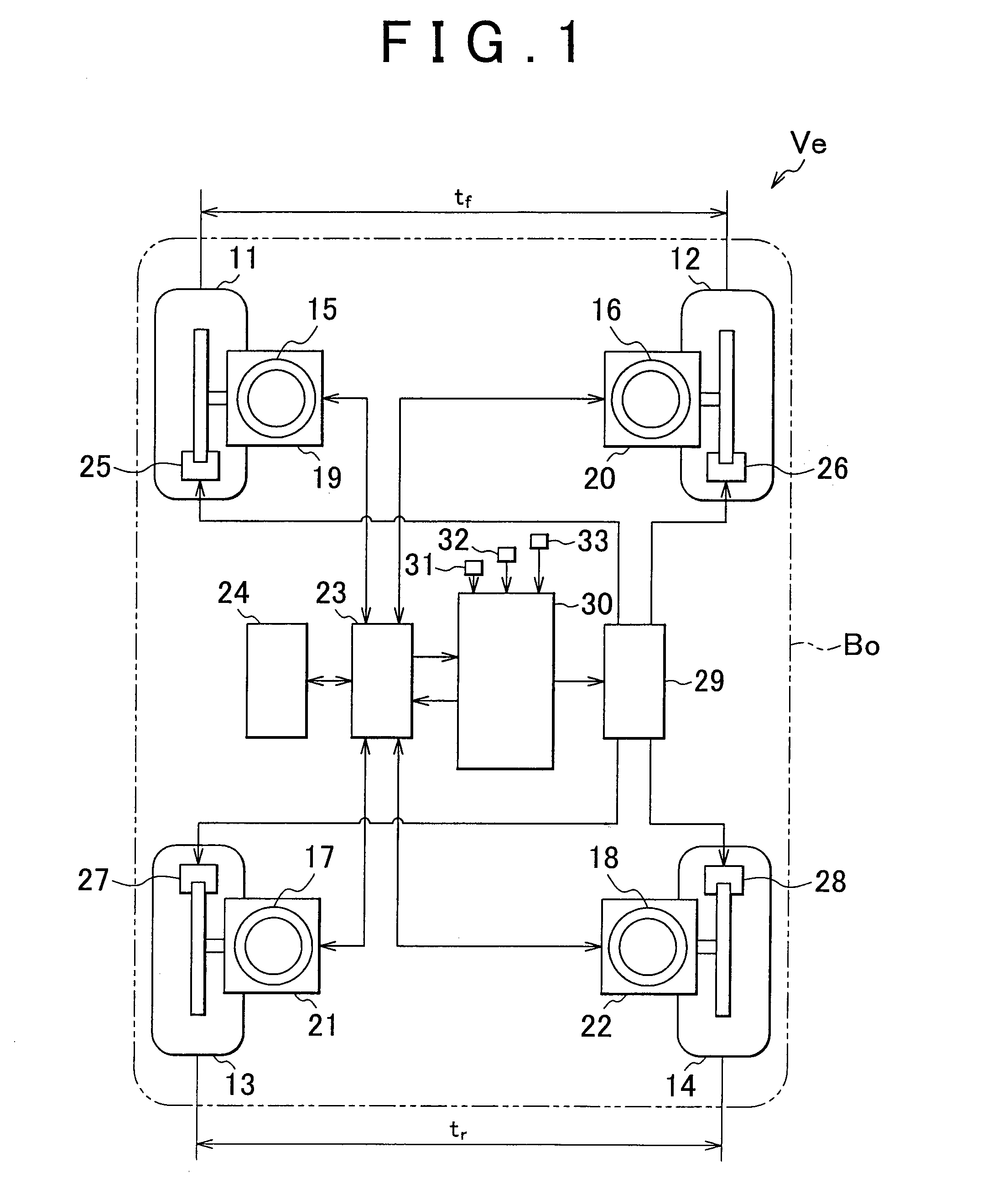
[0025]Hereinafter, an embodiment of the invention will be described in detail with reference to the accompanying drawings. FIG. 1 schematically shows the configuration of a vehicle Ve equipped with a vehicle braking / driving force control system according to embodiments.

[0026]The vehicle Ve includes left and right front wheels 11 and 12 and left and right rear wheels 13 and 14. Then, the left and right front wheels 11 and 12 are supported by a vehicle body Bo of the vehicle Ve via respective suspension mechanisms 15 and 16 independently of each other. That is, the vehicle body Bo is supported by the springs (supported by the suspension mechanisms). In addition, the left and right rear wheels 13 and 14 are supported together by the vehicle body Bo of the vehicle Ve via respective suspension mechanisms 17 and 18. Or the left and right rear wheels 13 and 14 are supported by the vehicle body Bo of the vehicle Ve via respective suspension mechanisms 17 and 18 independen...

second embodiment

b. Second Embodiment

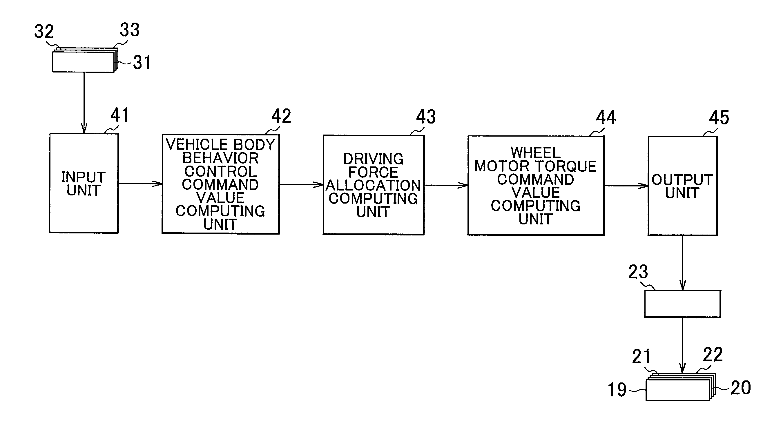
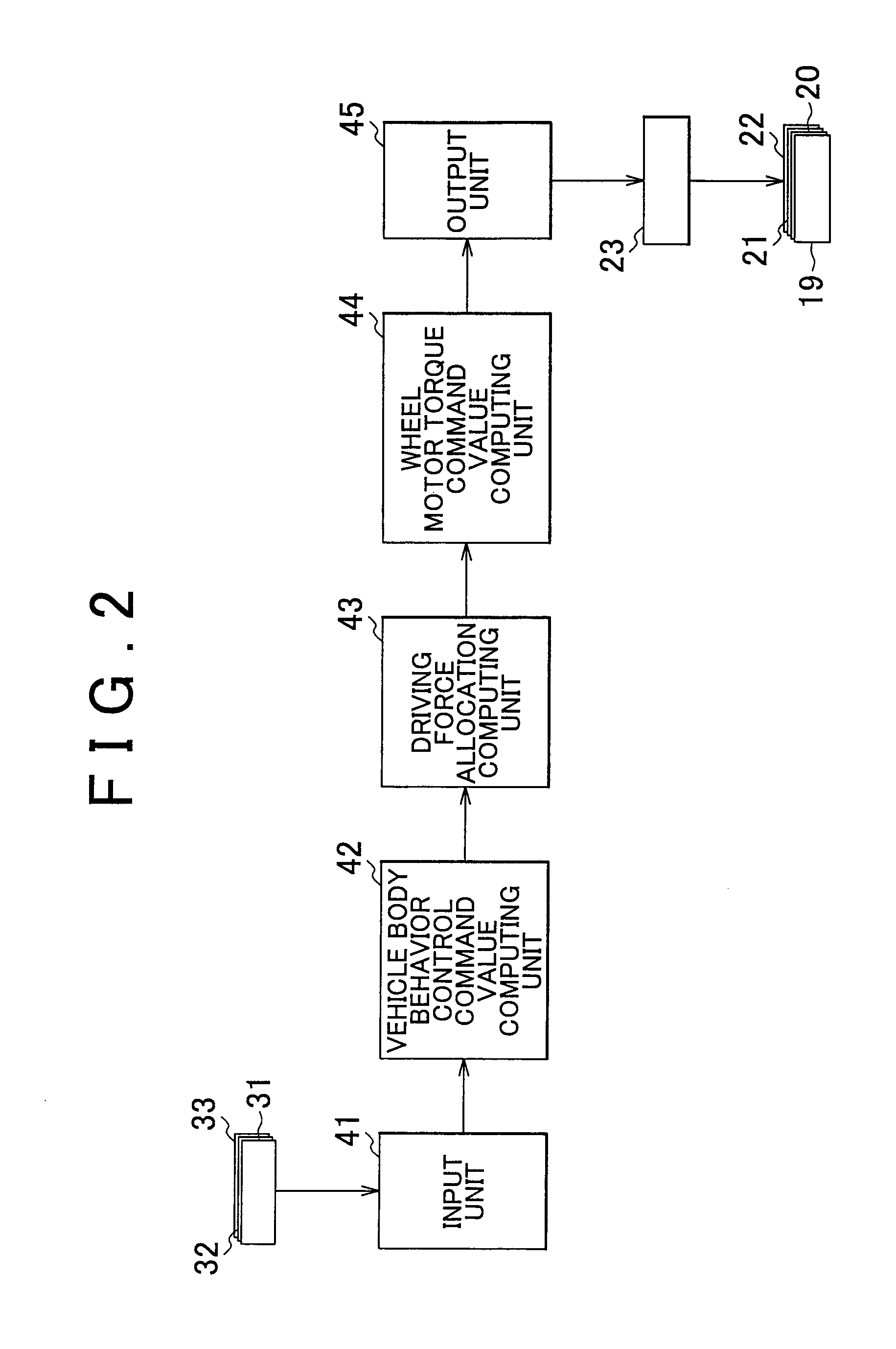
[0052]Next, a second embodiment of the invention will be described. In the first embodiment, in order to generate the target longitudinal driving force FX, target roll moment Mx, target pitch moment My and target yaw moment Mz computed by the vehicle body behavior control command value computing unit 42, the driving force allocation computing unit 43 computes the front left driving force Ffl, the front right driving force Ffr, the rear left driving force Frl and the rear right driving force Frr, and the wheel motor torque command value computing unit 44 computes the motor torques Tfl, Tfr, Trl and Trr. Then, in the first embodiment, the in-wheel motors 19 to 22 respectively generate the computed motor torques Tfl, Tfr, Trl and Trr.

[0053]In this case, when a plurality of behaviors of the vehicle body Bo are controlled, for example, a driving force (or a braking force) in any one of the wheels 11 to 14, that is, a motor torque required of any one of the in-wheel mo...


PUM


Abstract

Braking/driving force control that includes: detecting a driver's operating state for causing the vehicle to run; detecting a vehicle body motional state while the vehicle is running; computing a target longitudinal driving force for causing the vehicle to run and motional state amounts for controlling a vehicle body behavior on the basis of the detected operating state and motional state; and computing driving or braking forces allocated to the wheels so as to achieve the computed target longitudinal driving force and target motional state amounts and that the braking/driving force generating mechanism causes the wheels to generate independently.

Description

BACKGROUND OF THE INVENTION[0001]1. Field of the Invention[0002]The invention relates to a vehicle braking / driving force control system and vehicle braking / driving force control method that individually control driving force or braking force to be generated by each wheel of the vehicle.[0003]2. Description of Related Art[0004]In recent years, there has been developed a so-called in-wheel motor-type vehicle as one mode of an electric vehicle. In the in-wheel motor-type vehicle, an electric motor (motor) is arranged inside or near each wheel, and each wheel is directly driven by the electric motor. In the in-wheel motor-type vehicle, electric motors provided respectively for wheels (drive wheels) are individually subjected to rotation control, that is, the electric motors are individually subjected to power running control or regenerative control, to individually control driving torque or braking torque applied to each drive wheel to thereby make it possible to appropriately control t...

Claims


Application Information

Patent Timeline
Patent Type & Authority Applications(United States)
IPC IPC(8): B60L7/18B60L15/20
CPCB60T8/17555Y02T10/648B60T2260/06B60T2270/302B60T2270/303B60L7/18B60L15/20B60L7/14B60L7/26B60L11/1803B60L15/2009B60L2220/14B60L2220/44B60L2240/12B60L2240/14B60L2240/24B60L2240/423B60L2250/26B60L2260/28B60L2270/145Y02T10/7258Y10S903/93Y10S903/947Y02T10/7005Y02T10/7275B60T8/1769Y02T10/72B60L50/51Y02T10/64Y02T10/70
Inventor KATSUYAMA, ETSUO
Owner TOYOTA JIDOSHA KK
Why Eureka
Try Eureka