Liquid ejection apparatus

Active Publication Date: 2013-08-29
BROTHER KOGYO KK
View PDF2 Cites 10 Cited by
  • Summary
  • Abstract
  • Description
  • Claims
  • Application Information

AI Technical Summary

Benefits of technology

The patent aims to prevent the generation of bubbles and splash droplets of moisturizing liquid in a tank, which can lead to problems in liquid ejection. The technology aims to restrain the formation of bubbles and droplets, improving the viscosity and stability of the liquid in the ejection opening.

Problems solved by technology

However, according to the technology above, because the moisturization is carried out while bubbles are generated in the tank, splash droplets of the moisturizing liquid are generated along with the bubbles in the tank, and the droplets may enter an outflow path.

Method used


Image

  • Liquid ejection apparatus
  • Liquid ejection apparatus
  • Liquid ejection apparatus

Examples


Embodiment Construction

[0030]The following will describe a preferred embodiment of the present invention with reference to figures.

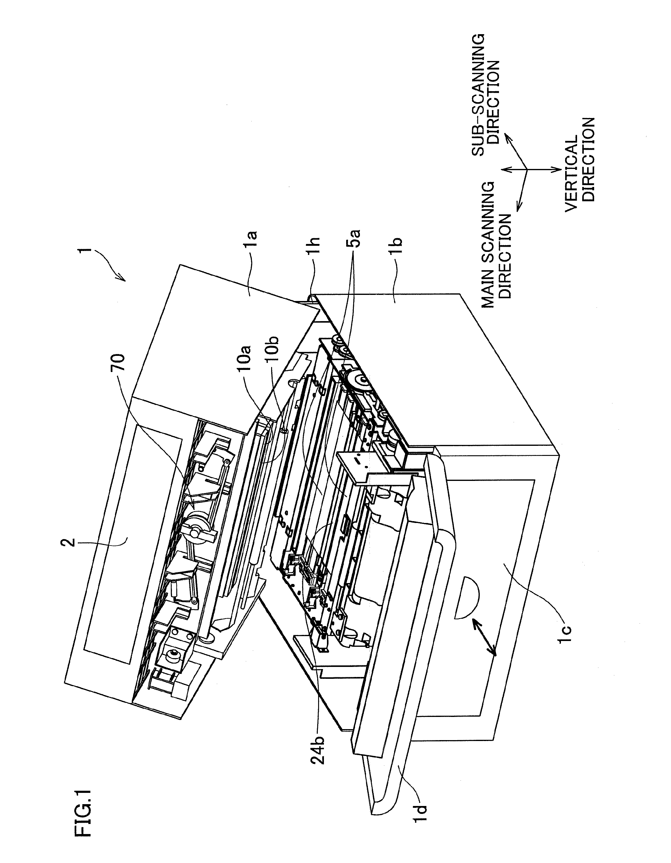
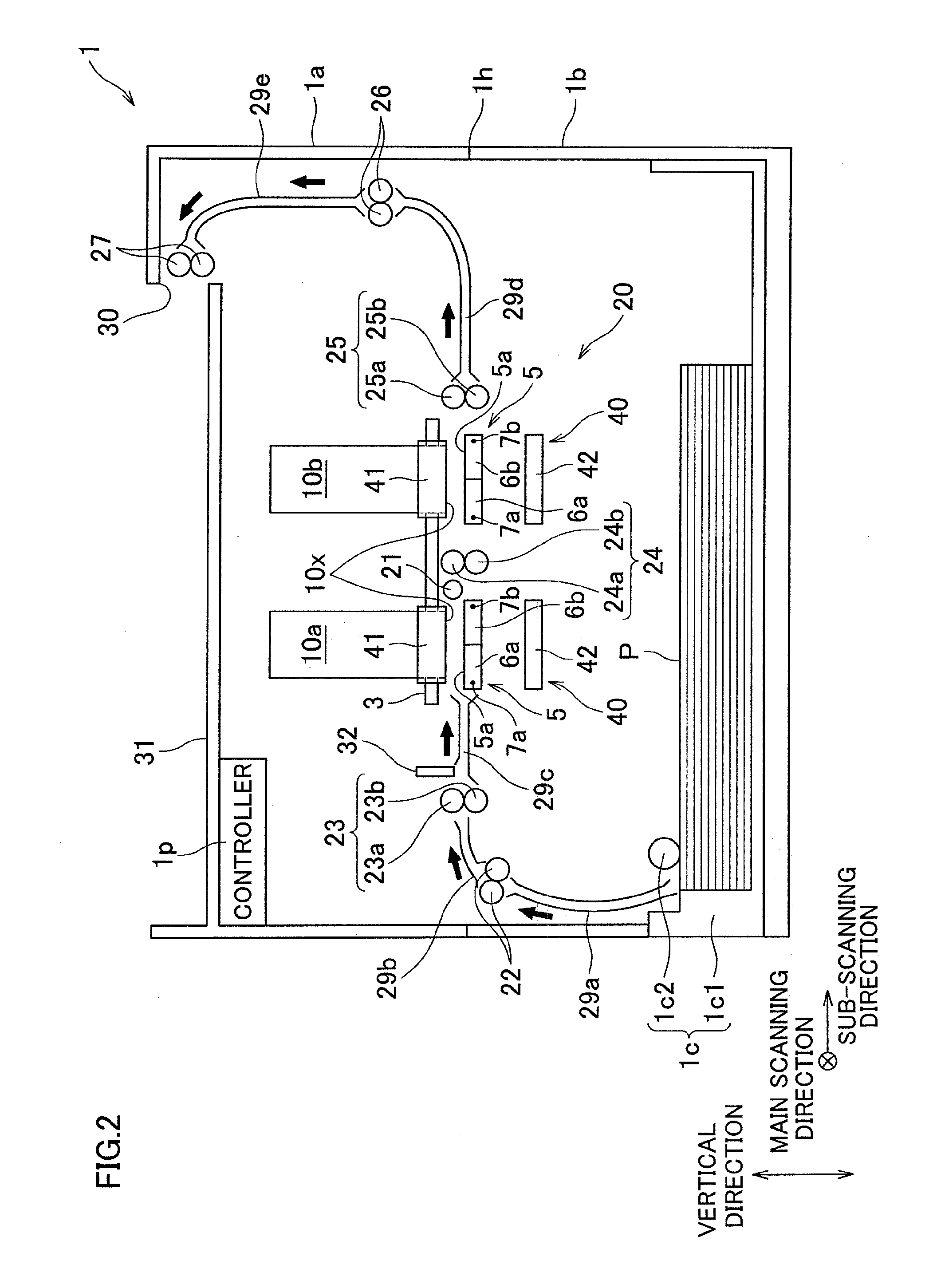
[0031]To begin with, referring to FIG. 1 and FIG. 2, the overall structure of an inkjet printer 1 of First Embodiment of the present invention will be described.

[0032]The printer 1 includes an upper housing 1a and a lower housing 1b which are both rectangular parallelepiped and are substantially identical in size. The upper housing 1a is an open-bottom box whereas the lower housing 1b is an open-top box. As the upper housing 1a is put on the lower housing 1b so that each closes the opening of the other, the space inside the printer 1 is defined (see FIG. 2).

[0033]On the top plate of the upper housing 1 a is provided a sheet discharge section 31. In the space defined by the housings 1a and 1b, a conveying path on which sheets P are conveyed is formed from a sheet supply unit 1c toward a sheet discharge section 31, along the thick arrows shown in FIG. 2.

[0034]The upper housing 1...


PUM


Abstract

An inflow opening of an inflow path opens to a space in a tank. An outflow opening of an outflow path opens to the space in the tank. The inflow opening and the outflow opening are vertically above a maximum level of the moisturizing liquid allowed to be stored in the tank.

Description

CROSS REFERENCE TO RELATED APPLICATION[0001]The present application claims priority from Japanese Patent Application No 2012-042981, which was filed on Feb. 29, 2012, the disclosure of which is incorporated herein by reference in its entirety.BACKGROUND OF THE INVENTION[0002]1. Field of the Invention[0003]The present invention relates to a liquid ejection apparatus capable of ejecting liquid such as ink.[0004]2. Description of Related Art[0005]In connection with liquid ejection apparatuses, a technology of moisturizing an ejection space opposing an ejection surface of a head while isolating the ejection space from its surrounding space by a capping mechanism has been known. For example, a known technology is arranged such that air in the ejection space is supplied to a tank, moisturization is conducted while generating bubbles in the tank, and then the moisturized air is sent back to the ejection space.SUMMARY OF THE INVENTION[0006]However, according to the technology above, because...

Claims


Application Information

Patent Timeline
IPC IPC(8): B41J2/165
CPCB41J2/16585B41J2/165
Inventor TAMAKI, SHUICHI
Owner BROTHER KOGYO KK
Why Eureka
Try Eureka