
Liquid droplet jetting apparatus

a technology of liquid droplets and jetting apparatus, which is applied in the field of liquid droplet jetting apparatus, can solve the problems of increased ink cartridge number, increased cost, and large printer size, and achieve the effects of suppressing the increase in liquid viscosity in the tubes, reducing the cost required for the tubes, and shortening the total length of tubes

Active Publication Date: 2009-06-04
BROTHER KOGYO KK
View PDF8 Cites 6 Cited by
  • Summary
  • Abstract
  • Description
  • Claims
  • Application Information

AI Technical Summary

Benefits of technology

[0010]An object of the present invention is to shorten the length of the tubes by connecting a liquid tank and two liquid droplet jetting heads in series. Another object of the present invention is to decrease the frequency of the recovery operation by arranging, on the downstream side in the liquid supply direction, a head in which the drying (increase in viscosity) is hardly caused in a nozzle and which suffers less influence on the jetting performance even when the viscosity-increased liquid and / or the air bubbles is / are supplied.

Problems solved by technology

However, when a plurality of ink cartridges are provided in the printer corresponding to the plurality of ink-jet heads respectively, then the number of the ink cartridges is increased, the cost is increased, and the printer is large-sized.
When one ink cartridge is connected to two ink-jet heads individually (in parallel) by means of a plurality of tubes, the total length of the tubes is consequently long as compared with a case in which one ink cartridge and two ink-jet heads are connected in series, which results in the increase in the cost.
When the tubes are made of resin, and the tubes have the gas permeability to some extent, then the following problem arises.
As described above, the ink containing a large amount of air bubbles and the viscosity-increased ink generated in the tubes bring about a large factor to cause the jetting failure in the nozzle.
The jetting failure of the nozzle is frequently caused.
In other words, the jetting failure tends to arise in the nozzle of the one head which is separated far from the ink cartridge.

Method used


Image

  • Liquid droplet jetting apparatus
  • Liquid droplet jetting apparatus
  • Liquid droplet jetting apparatus

Examples


Embodiment Construction

[0058]Next, an embodiment of the present invention will be explained. This embodiment is an example in which the present invention is applied to a printer provided with two types of heads, i.e., a fixed type line head and a serial head.

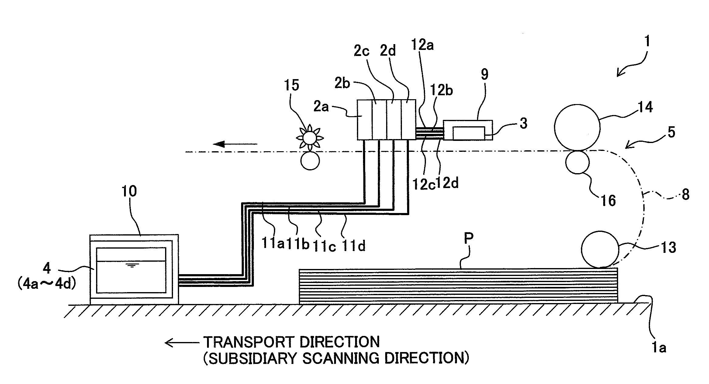
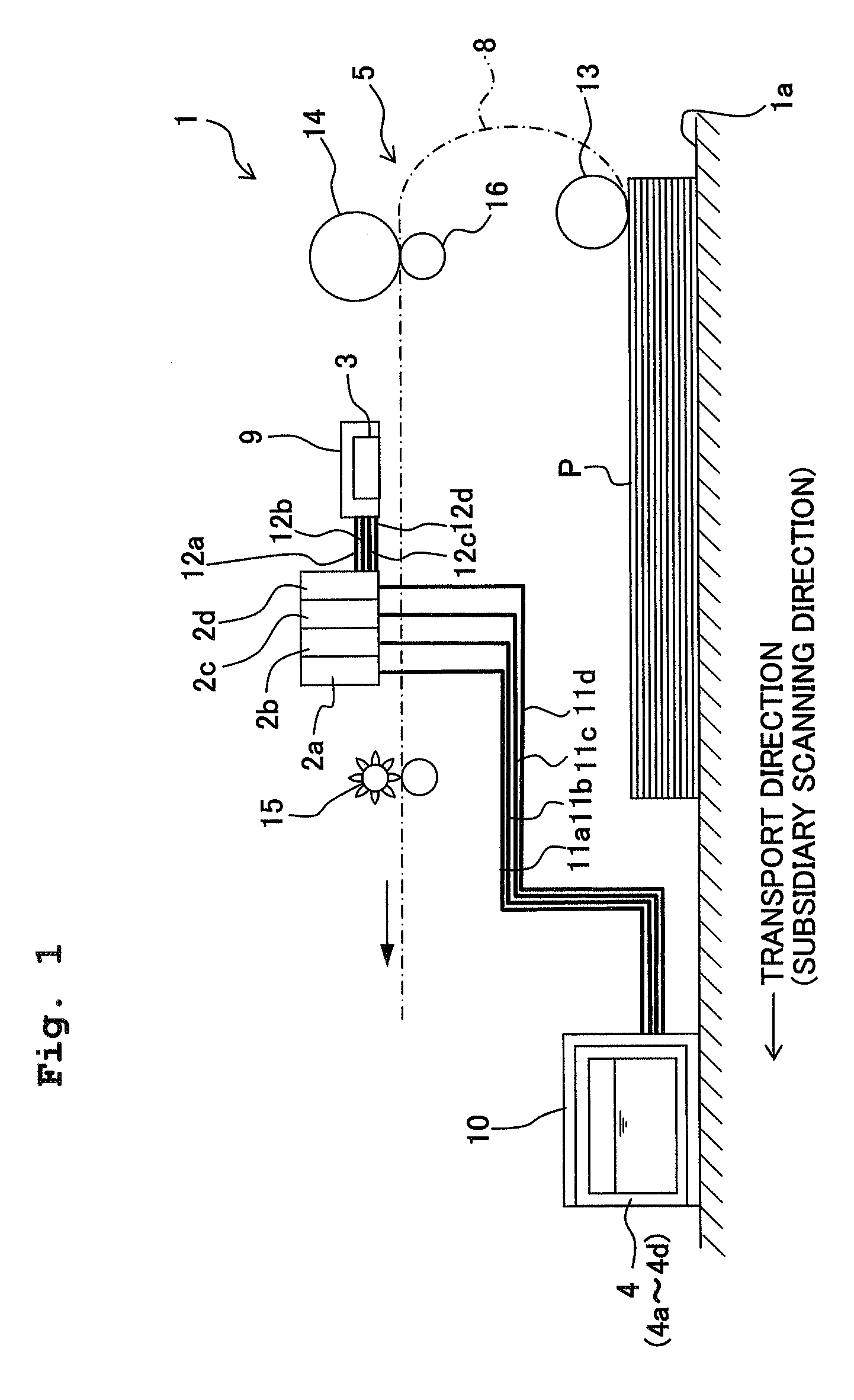
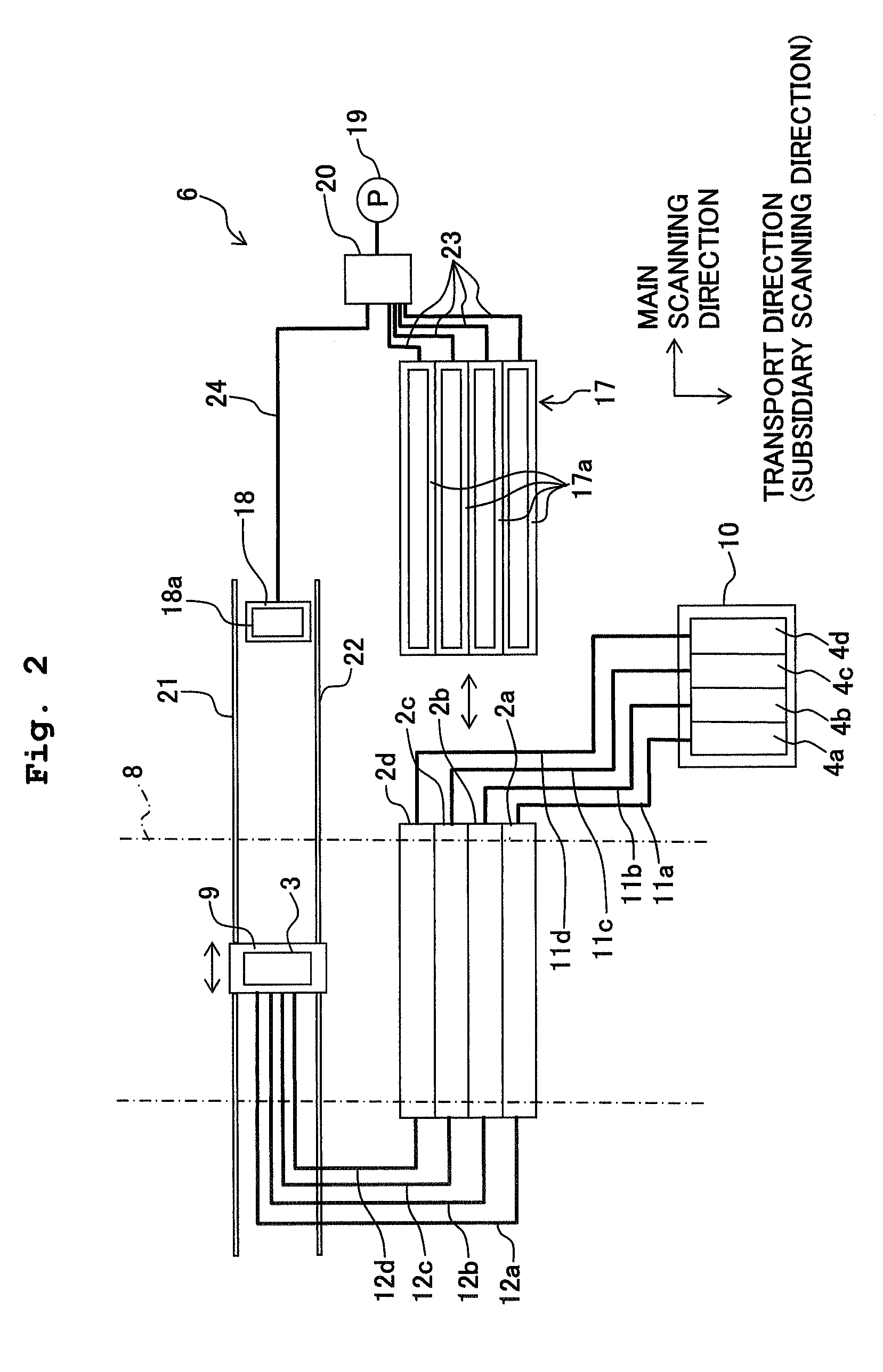
[0059]FIG. 1 shows a schematic side view illustrating the printer 1 of this embodiment. FIG. 2 shows a plan view illustrating the printer 1 shown in FIG. 1. In FIG. 2, for example, rollers 13, 14, 15 shown in FIG. 1 are omitted from the illustration.

Overall Arrangement of Printer

[0060]As shown in FIGS. 1 and 2, the printer 1 (liquid droplet-jetting apparatus) of this embodiment comprises, for example, four first heads 2a to 2d of fixed line type (first liquid droplet-jetting heads), a serial type second head 3 (second liquid droplet-jetting head); four ink cartridges 4a to 4d (liquid storage containers, liquid tanks) which store four types (four colors) of inks respectively, a printing paper transport mechanism 5 (transport mechanism) which transports...


PUM


Abstract

A printer comprises a fixed line type first head, a serial type second head, an ink cartridge which stores an ink to be supplied to the first and second heads, a first cap which is to be installed to the first head, and a second cap which is to be installed to the second head. The ink cartridge and the first and second heads are connected in series in this order by using tubes. Accordingly, it is possible to shorten the lengths of the tubes. The serial type head, in which the drying is hardly caused from a nozzle and the influence is exerted to a small extent on the jetting performance when any viscosity-increased liquid and / or bubbles is / are supplied, is arranged on the downstream side. Accordingly, it is possible to decrease the frequency of the recovery operation.

Description

CROSS REFERENCE TO RELATED APPLICATION[0001]The present application claims priority from Japanese Patent Application No. 2007-309963, filed on Nov. 30, 2007, the disclosure of which is incorporated herein by reference in its entirety.BACKGROUND OF THE INVENTION[0002]1. Field of the Invention[0003]The present invention relates to a liquid droplet jetting apparatus for jetting liquid droplets.[0004]2. Description of the Related Art[0005]In general, an ink-jet printer, which records images, letters or the like on a recording medium such as the printing paper, comprises an ink-jet head (liquid droplet jetting head) which has nozzles for jetting liquid droplets of the ink, and an ink cartridge (liquid storage container, ink tank) for storing the ink to be used for the ink-jet head. Usually, the ink-jet head and the ink cartridge are connected to one another by means of a tube made of resin. The ink, which is stored in the ink cartridge, is supplied to the ink-jet head via the tube.[0006]...

Claims


Application Information

Patent Timeline
Patent Type & Authority Applications(United States)
IPC IPC(8): B41J2/165
CPCB41J2/16532B41J3/543B41J2/16585
Inventor KUBO, TOMOYUKIUMEDA, TAKAICHIROKATO, RYUJISAKURAI, HISAKI
Owner BROTHER KOGYO KK
Learn More