Pump

a technology of pump and pump body, applied in the field of pumps, can solve problems such as the difficulty of pumping efficiently using other types of pumps

Inactive Publication Date: 2005-01-27
PIERBURG PUMP TECH UK
View PDF8 Cites 6 Cited by
  • Summary
  • Abstract
  • Description
  • Claims
  • Application Information

AI Technical Summary

Benefits of technology

[0007] Since the viscosity of a fluid depends on the temperature of the fluid, by virtue of the invention, the pumping efficiency of the pump when used to pump a fluid of variable temperature may be improved.
[0009] Since the viscosity of a liquid decreases with increasing temperature, by virtue of the invention, the pumping efficiency of the pump when used to pump a liquid of variable temperature may be improved.
[0013] Since the viscosity of a liquid lubricant decreases with increasing temperature, and the temperature of the lubricant increases as the engine warms up, by virtue of the invention, the pumping efficiency of the lubricant pump may be improved.
[0015] The auxiliary pump may thus be used before the engine is warmed up relatively efficiently to pump cold, viscous liquid lubricant, such as oil, around the engine, the efficiency of the auxiliary pump being at least maintained as the lubricant warms up by virtue of the changing plate separation, and the main pump may be used only once the lubricant has reached its optimum operating temperature, thus to pump relatively low viscosity liquid lubricant. Thus, by virtue of the invention, the main pump may be chosen to pump efficiently low viscosity warm lubricant, whilst energy losses through use of an unsuitable main pump to pump cold, viscous lubricant around the engine, may be avoided.
[0017] When the pump is operating at below optimum efficiency, energy is lost through frictional forces generated by adjacent fluid lamina moving at different velocities, and the energy thus lost is converted to heat which increases the temperature of the lubricant. Thus, whilst the lubricant is below the optimum operating temperature, the auxiliary pump acts not only to pump lubricant around the engine, but also may assist in heating the lubricant, so that the lubricant reaches its optimum operating temperature more rapidly.
[0020] Operation of the auxiliary pump prior to engine start up ensures that there is lubricant present in the engine when the engine starts, and thus reduces wear of the engine.

Problems solved by technology

Since operation of a disc pump relies on the viscosity of the pumped fluid, disc pumps may advantageously be used to pump relatively viscous fluids, which can be difficult to pump efficiently using other types of pump.

Method used


Image

  • Pump
  • Pump
  • Pump

Examples


Embodiment Construction

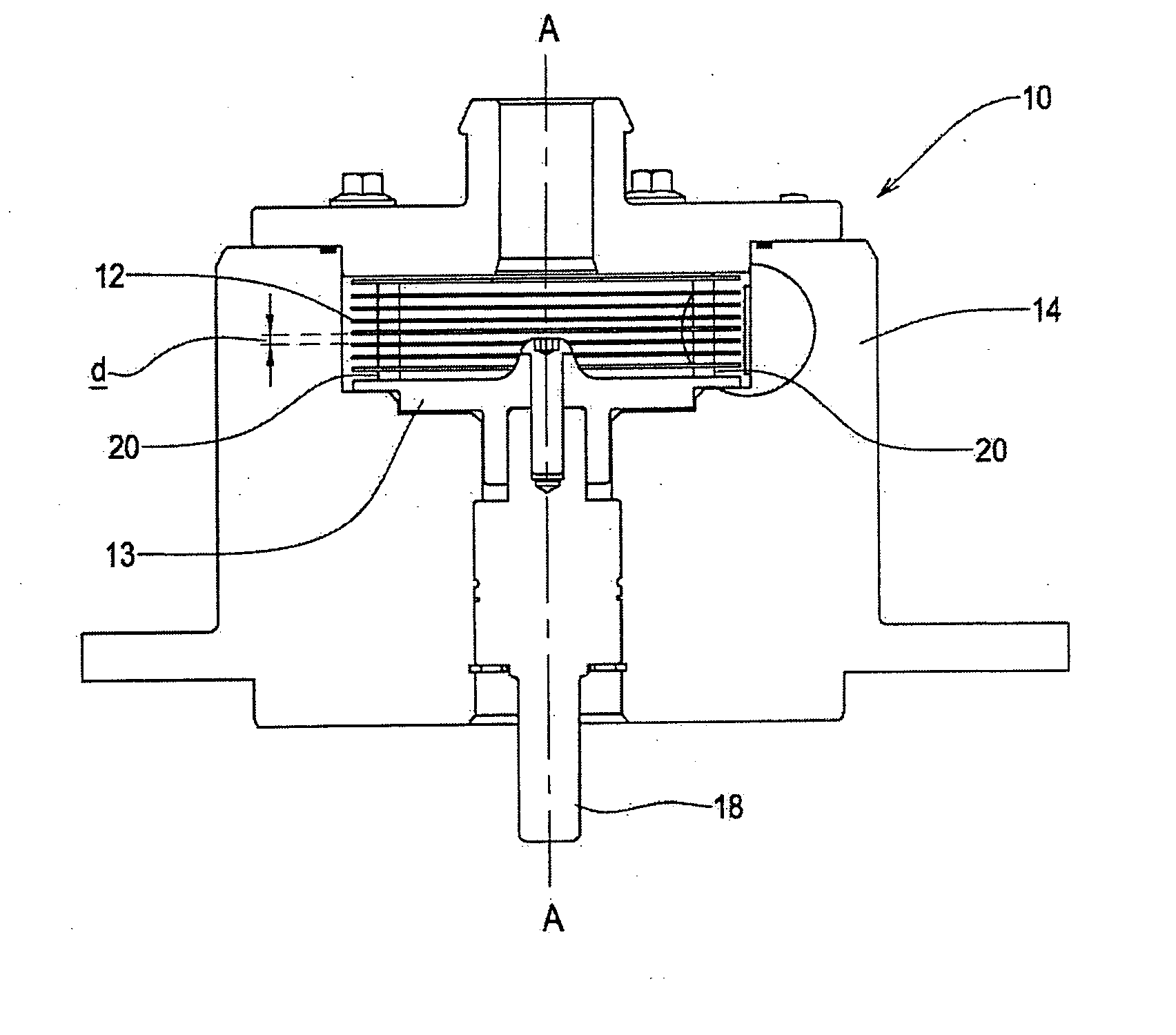
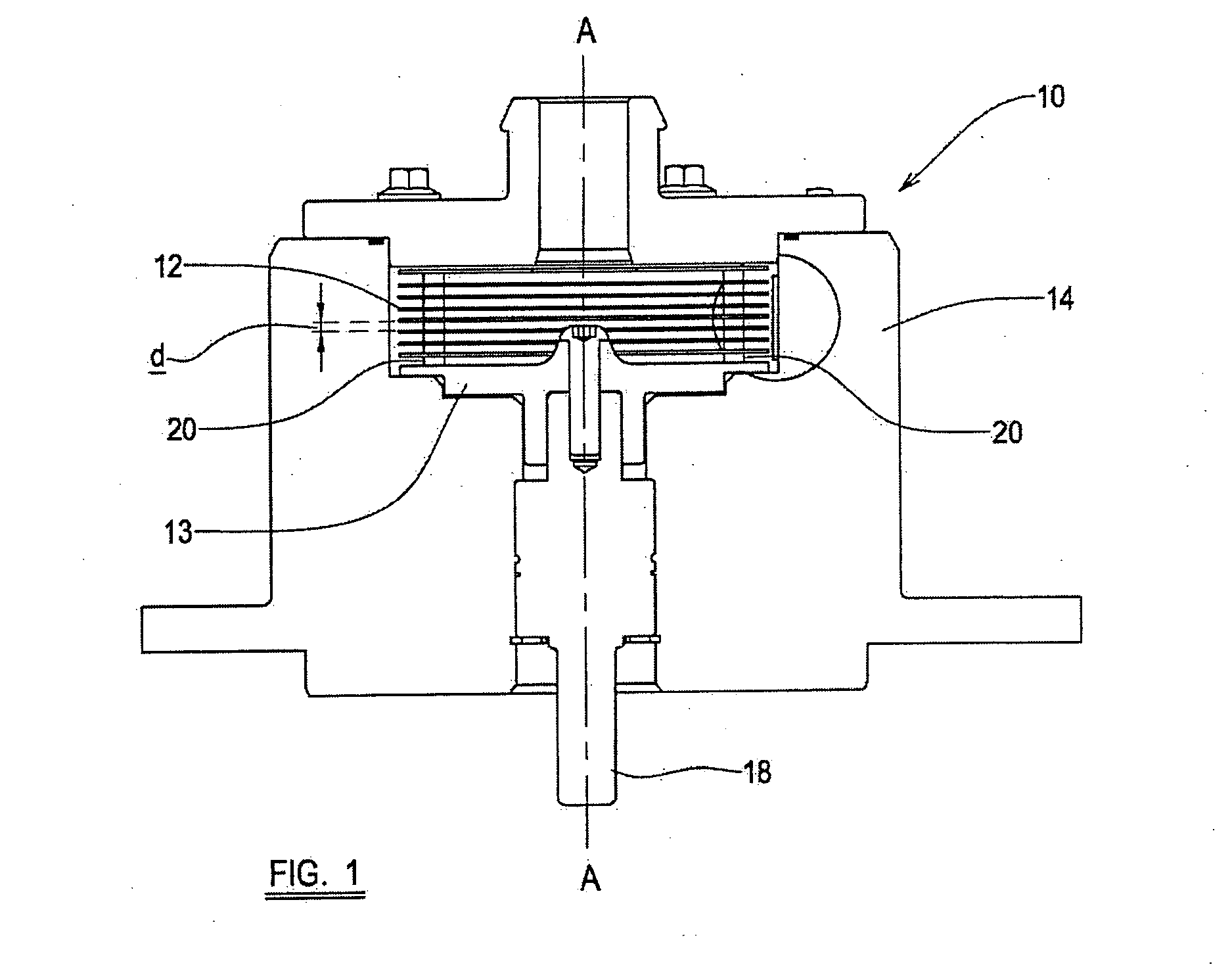
[0028] Referring now to FIG. 1, there is shown a pump 10 including a plurality of spaced apart generally mutually parallel plates 12, which in this example are generally circular discs. The discs 12 are supported on a base plate 13, and mounted for rotation in a housing 14 about an axis A which extends generally normal to the discs 12, to effect pumping of a fluid within the housing 14, from an inlet to an outlet provided in the housing 14. Rotation of the discs 12 is achieved by the operation of a driving means (not shown), in this case an electric motor, which is connected to the base plate 13 by means of a drive shaft 18.

[0029] Pumping of fluid within the housing 14 is achieved as follows. When a fluid enters the housing 14 via the inlet, a layer of fluid adheres to the surfaces of the discs 12, forming a so-called boundary layer that remains stationary relative to the rotating discs 12. As the discs 12 rotate about axis A, the effects of boundary-layer adhesion and viscous drag...


PUM


Abstract

A pump including a plurality of spaced apart generally mutually parallel plates, which are mounted for rotation in a housing about an axis which extends generally normal to the plates, to effect pumping of a fluid, wherein the separation of the plates varies depending on the temperature of fluid within the housing.

Description

[0001] This application claims priority to United Kingdom Patent Application No. 0317388.7 filed Jul. 25, 2003, the entire disclosure of which is incorporated herein by reference FIELD OF THE INVENTION [0002] The present invention relates to a pump, particularly, but not exclusively for use in pumping lubricant such as oil into an engine. DESCRIPTION OF THE PRIOR ART [0003] Pumps in which pumping is effected by means of a plurality of generally parallel discs or annular plates which rotate together in the fluid to be pumped about an axis generally normal to the plates are known, and are generally referred to as disc pumps. When a fluid enters the pump, layers of fluid adhere to the surfaces of the discs, forming so-called boundary layers that remain stationary relative to the rotating discs. As the discs rotate, the effects of boundary-layer adhesion and viscous drag cause fluid between the discs to be pulled around the pump with the discs. Energy is transferred to successive layers...

Claims


Application Information

Patent Timeline
Patent Type & Authority Applications(United States)
IPC IPC(8): F01M1/02F04D5/00F04D15/00F16N13/00
CPCF01M1/02F16N13/00F04D15/0038F04D5/001
Inventor WILLIAMS, DAVID JOHNCOOPE, NEALBLACK, DAVID THOMAS
Owner PIERBURG PUMP TECH UK
Why Eureka
Try Eureka