
Pump shaft bearing support

a technology for pump shafts and bearings, which is applied in the direction of piston pumps, positive displacement liquid engines, borehole/well accessories, etc., can solve the problems of irreparable damage to the pump, inability to adjust the lift capacity of the pump, and inability to run the pump dry, etc., to achieve the effect of low cost and modification of the pump lift capacity

Inactive Publication Date: 2012-03-29
SUBMERSIBLE PUMPS
View PDF5 Cites 9 Cited by
  • Summary
  • Abstract
  • Description
  • Claims
  • Application Information

AI Technical Summary

Benefits of technology

[0010]Therefore, it is desirable to provide a low cost method of matching pump lift components with well capacity. The pump lift capacity of a pump can be modified by the replacement of one or more stages with a shaft bearing support of the invention.
[0011]By adding the shaft bearing support of the invention, a given housing can be used with the exact number of stages required to effectively pump fluid out of a well, which allows for a well to be pumped without running the well dry and without leaving any fluid below. This invention will maximize profits and efficiency while minimizing wear and tear on the equipment.
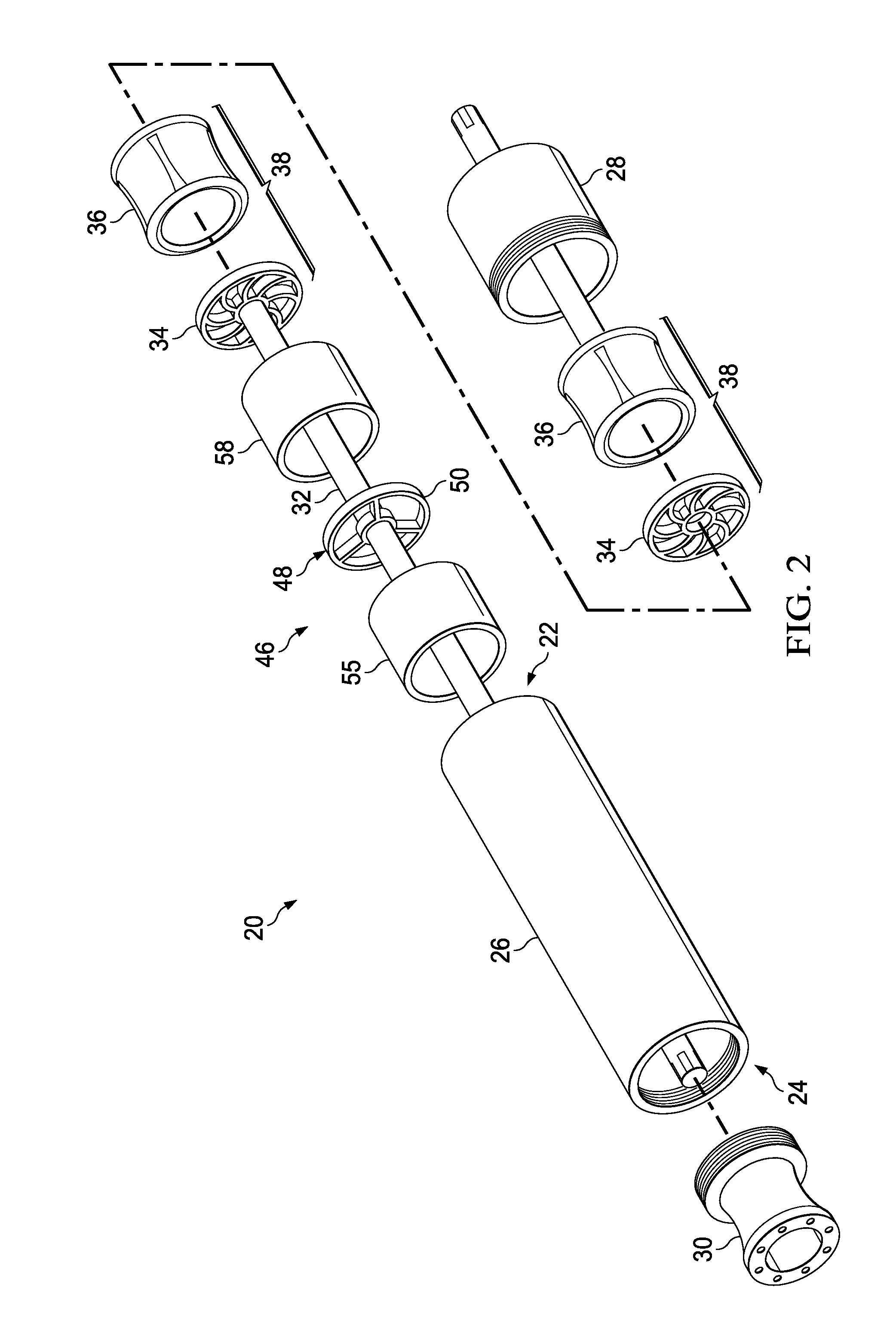
[0012]The shaft bearing support of the invention is made up of several features. The outside diameter of the shaft bearing support is an outer ring that fits inside a pump housing. Webs connect the outer ring to an inner ring, which defines an inside diameter of the shaft bearing support. Therefore, the inner ring is fixed relative to the outside diameter ring. Both the outer and inner rings have a sufficient width and depth to be mechanically sound. The inner ring of the shaft bearing support has an inner diameter (ID) that is large enough to allow the pump shaft to pass therethrough and to accommodate a fluid bearing between the pump shaft and the ID of the inner ring. The webs of the shaft bearing support define a volume or void between each web so that pumped fluid can move through the voids defined by the pump shaft bearing support with minimal obstruction or frictional loss.

Problems solved by technology

An incorrectly sized pump runs the risk of getting stuck in the casing.
First, lifting more fluid than the well can produce will run a pump dry and irreparably damage the pump.
Therefore, sizing the pump is critical.
In the past, pump manufactures were only able to get close to providing a pump with the amount of stages to exactly match lift with well capacity.
This is due to limitations imposed by commonly available housing lengths and stage configurations.
A disadvantage with this solution is that the use of tandem pumps is a costly solution to the customer.
A disadvantage associated with the use of VSDs is that VSDs are relatively expensive and costly to operate, thus costing the customer more.

Method used


Image

  • Pump shaft bearing support
  • Pump shaft bearing support
  • Pump shaft bearing support

Examples


Embodiment Construction

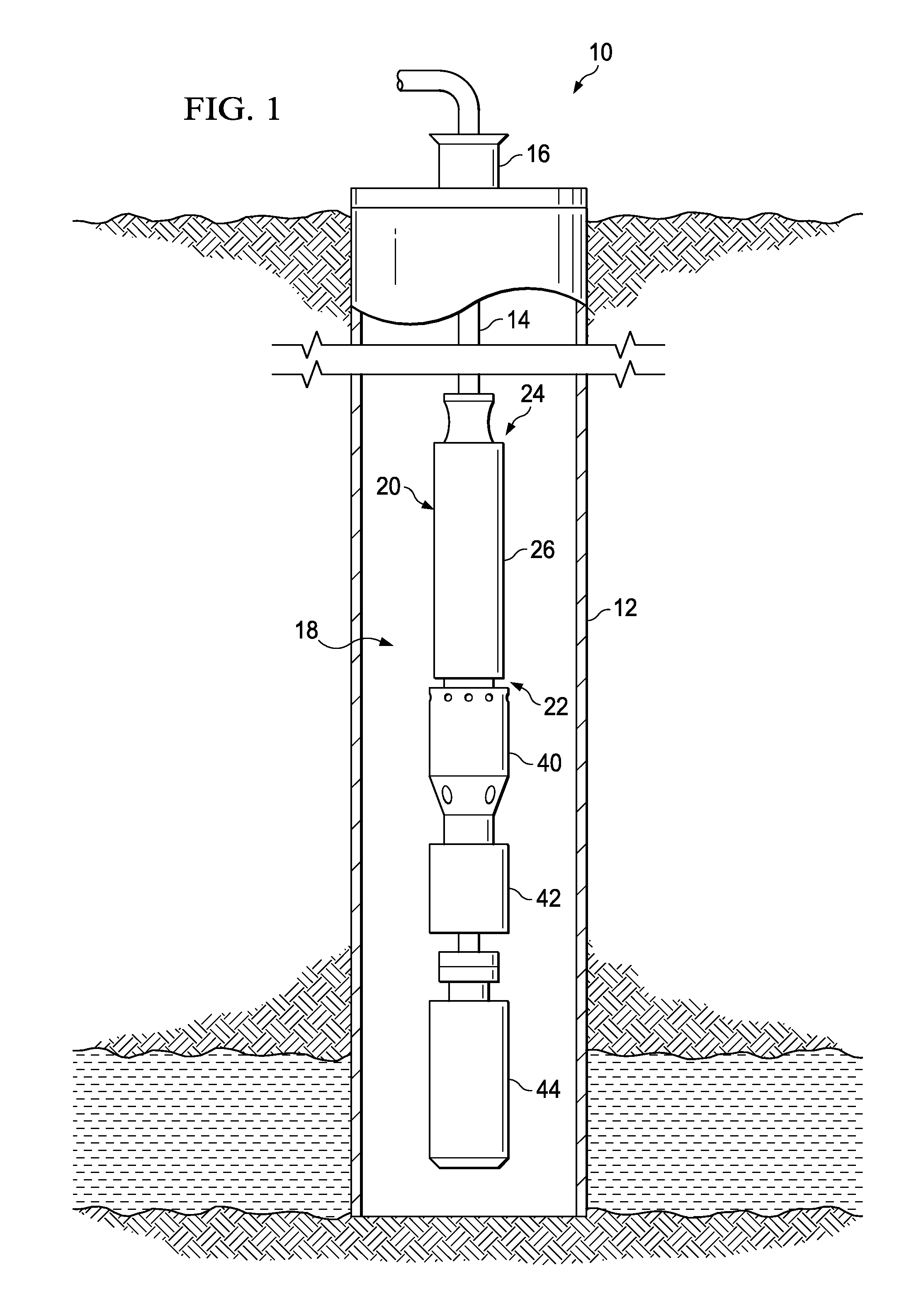
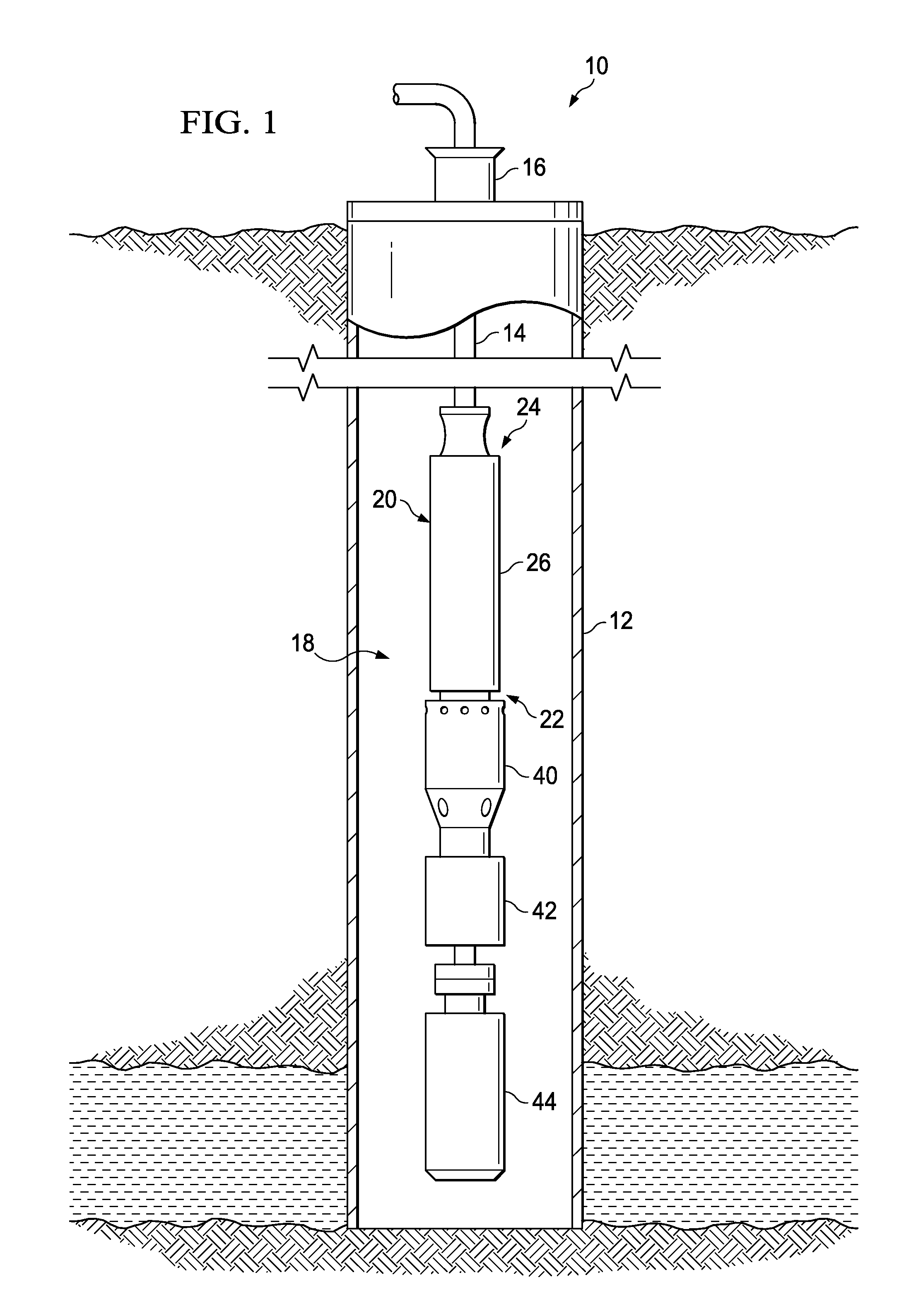
[0017]Referring now to FIG. 1, shown is a well designated generally 10. The well consists of casing 12. Tubing 14 extends downwardly into casing 12 from wellhead 16. An electrical submersible pump (ESP) unit, designated generally 18, is suspended from tubing 14. ESP unit 18 has a centrifugal pump unit 20. Pump unit 20 has an intake end 22 and an output end 24. Output end 24 is affixed to tubing 14 for delivering fluids to tubing 14.

[0018]Pump unit 20 further includes a housing 26. A pump base 28 (FIG. 2) is affixed to intake end 22 of housing 26. Pump head 30 is affixed to output end 24 of housing 26. Pump shaft 32 extends through housing 26. A plurality of impellers 34 are affixed to pump shaft 32 for rotating with pump shaft 32. A plurality of diffusers 36 are located adjacent to each of impellers 34 for directing fluid flow toward a center of an adjacent impeller 34. As shown in FIG. 2, each of said impellers 34 and diffusers 36 comprise a stage 38.

[0019]ESP unit 18 additionally ...


PUM


Abstract

A device and method of tailoring a pump lift capacity of a pump for an electrical submersible pumping unit (ESP). The pump unit of the ESP has a plurality of stages, each made up of an impeller and a diffuser. The ESP has a pump lift capacity, which is ideally matched with well capacity. The well capacity is, therefore, the target lift capacity. To facilitate matching of pump lift capacity and well capacity, one or more stages of the pump unit may be replaced with a spacer assembly to reduce pump lift capacity by a desired amount. The spacer assembly may include a shaft bearing support made up of an outer ring and an inner ring, wherein the outer and inner ring are connected by webs, which allow oil to flow through the support. The spacer assembly may be axially located on the pump shaft via compression tubes.

Description

FIELD OF THE INVENTION[0001]The invention relates to electrical submersible pumps. More particularly, the invention relates to replacing one or more pump stages with a spacer, or pump shaft bearing support, for fine tuning a pump's lift capacity to more closely match well capacity.BACKGROUND OF THE INVENTION[0002]Electrical submersible pumps (ESP) are used to artificially lift well fluid from deep underground. Primarily, ESPs are used to pump oil, typically as part of an oil and water mix, from deep wells at high pressures. ESPs are driven by long tubular, high horsepower, electric inductance motors that typically run at speeds of approximately 3,500 rpm. A common type of pump used in an ESP is a pump generally known as a centrifugal pump. Centrifugal pumps are made up of six (6) primary components. The major components are the housing, shaft, head, base, impeller and diffuser. The impeller and diffuser, when paired together, are referred to as stages.[0003]Pumps are designed, manuf...

Claims


Application Information

Patent Timeline
Patent Type & Authority Applications(United States)
IPC IPC(8): E21B43/00F04B35/04
CPCE21B43/128F04D29/0462F04D29/043F04D13/10
Inventor JANITZ, MIKEL ERIC
Owner SUBMERSIBLE PUMPS
Learn More