Vacuum sewage system

a sewage system and vacuum technology, applied in the direction of sewage draining, flushing devices, water closets, etc., can solve the problems of low degree of efficiency, large space requirements, and large solution requirements, and achieve the effect of reducing space requirements and effective sewage transportation

Active Publication Date: 2010-02-11
EVAC INT
View PDF5 Cites 9 Cited by
  • Summary
  • Abstract
  • Description
  • Claims
  • Application Information

AI Technical Summary

Benefits of technology

[0013]An object of the present invention is to provide a vacuum sewer system, which avoids the above mentioned problems and provides an effective sewage transport with a pump arrangem

Problems solved by technology

Due to the large volume collecting tank, such systems require a lot of space, which normally is not available in e.g. trains, marine vessels and aircraft.
This solution requires a lot of space.
Further, it has a low degree of efficiency.
This solution also requires a large space and furthermore the pump is very vulnerable to any humidity, thus requiring intricate control mechanisms.
The latter solutions with on-line pumps having the dual duty of generating vacuum by sucking air and simultaneously sucking sewage are, however, not very

Method used


Image

  • Vacuum sewage system
  • Vacuum sewage system
  • Vacuum sewage system

Examples


first embodiment

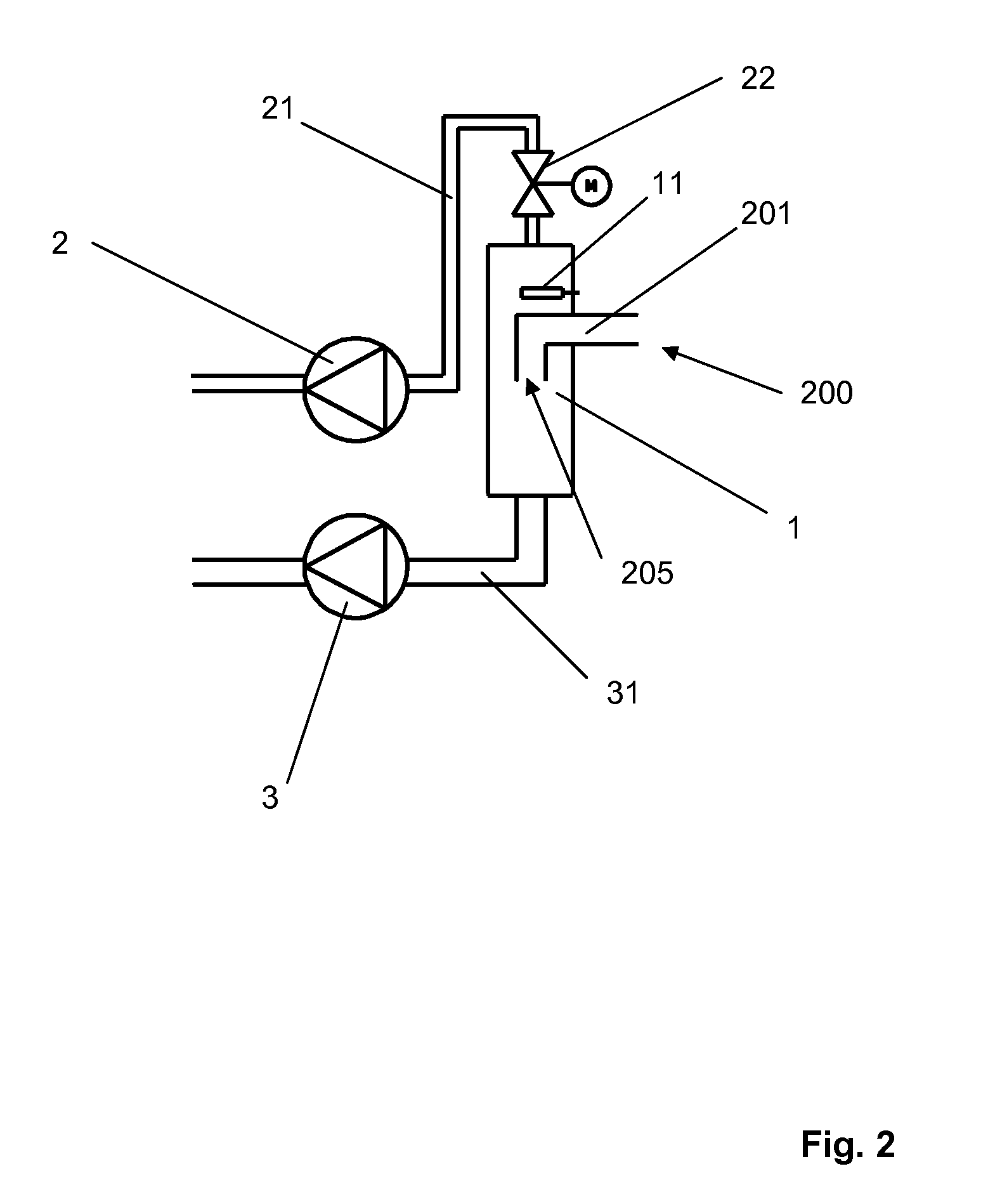
[0042]FIG. 2 shows the on-line separator device 1 with two pump means coupled in parallel to the on-line separator device 1. The first pump means 2 is a vacuum pump connected to the on-line separator device 1 by means of a conduit 21 provided with a first valve means 22, a shut-off valve, which is arranged on the suction side of the vacuum pump, between the vacuum pump and the on-line separator device 1. This first valve means 22 is not necessary for the appropriate functioning of the arrangement, but advantageous as a safety feature. The second pump means 3 is a liquid pump, which also should have the capacity to pump air, the suction side of which is connected to the on-line separator device 1 by means of a conduit 31. The two pump means are defined and discussed in more detail above.

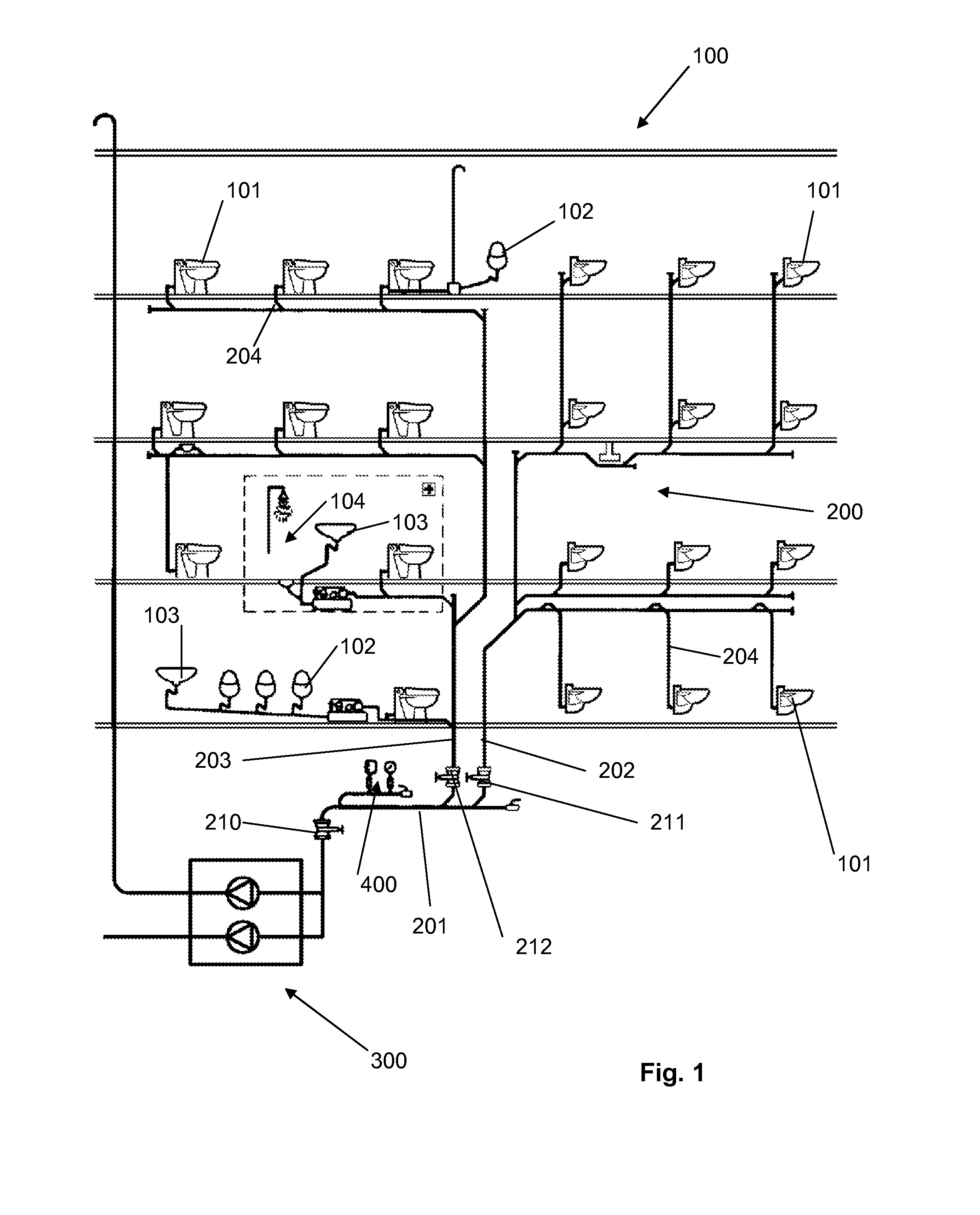
[0043]The on-line separator device 1 is arranged in the vacuum sewer piping 200. With particular reference to FIG. 1, it is arranged in connection with the collector 201, whereby the sewage flow in th...

second embodiment

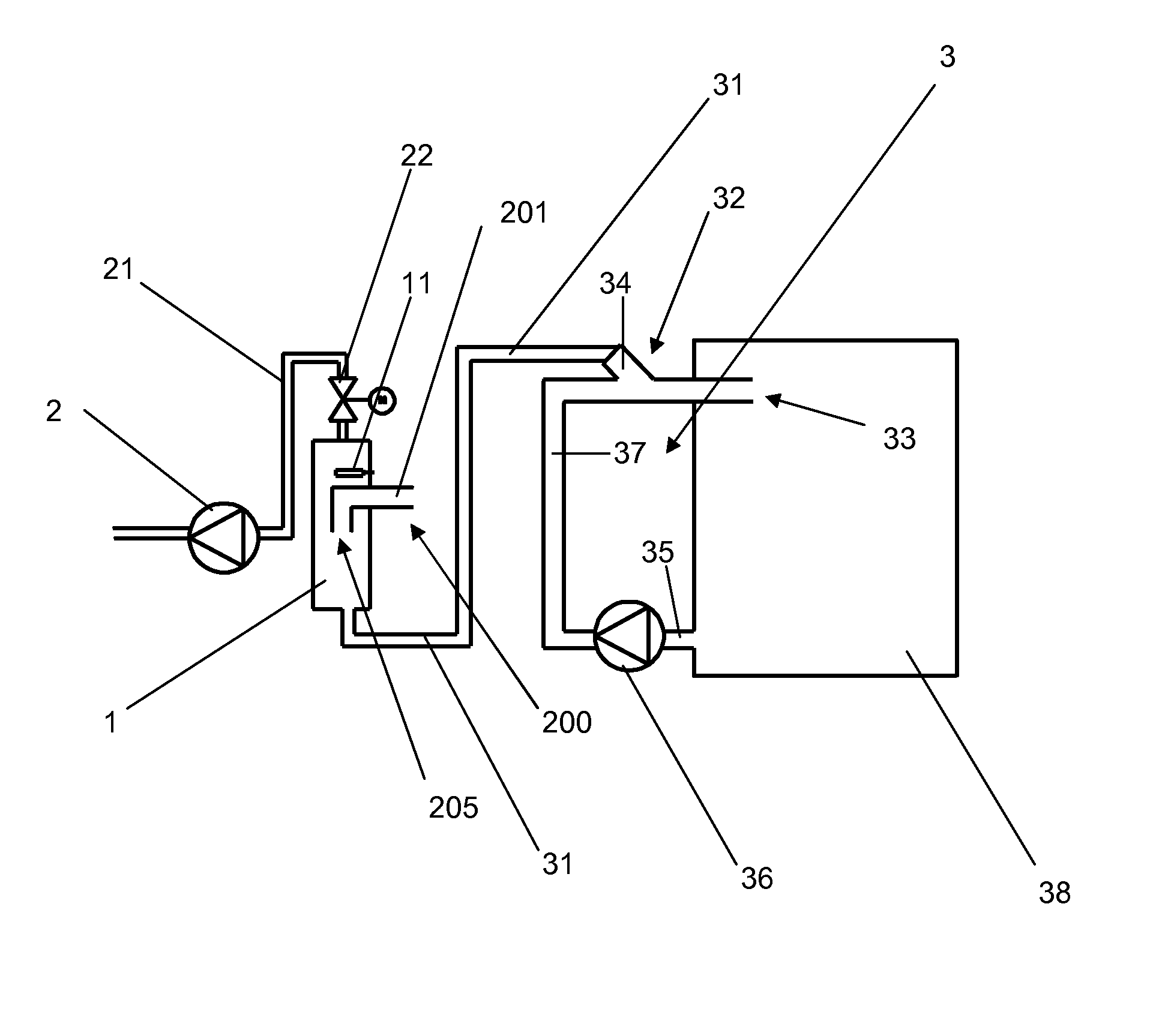
[0058]FIG. 3 shows the on-line separator device 1 with two pump means coupled in parallel to the on-line separator device 1. The first pump means 2 is a vacuum pump connected to the on-line separator device 1 by means of a conduit 21 provided with a first valve means 22, a shut-off valve, which is arranged on the suction side of the vacuum pump, between the vacuum pump and the on-line separator device 1. The second pump means 3 is connected to the on-line separator device 1 by means of a conduit 31. The second pump means 3 comprises a liquid jet pump 32 and a liquid pump 36 connected to a circulation tank 38. The liquid collected in the circulation tank 38 is circulated by the liquid pump 36 to the liquid jet pump 32 in order to produce a suction effect in the conduit 31 for pumping mainly sewage from the sewage flow flowing into the on-line separator device 1 and further into the circulation tank 38. The second pump means 3 corresponds to an ejector system. The two pump means are d...


PUM


Abstract

The invention relates to a vacuum sewage system, which includes a sanitary unit, such as a toilet unit, vacuum sewer piping (200) connected to the sanitary unit, a discharge valve between the sanitary unit and the vacuum sewer piping, and a vacuum generating device for generating vacuum in the vacuum sewer piping. The system comprises an on-line separator device (1) in the vacuum sewer piping (200, 201) and a first pump means (2) and a second pump means (3) connected in parallel with the on-line separator device (1). The first pump means (2) is a vacuum pump for generating vacuum in the vacuum sewer piping (200, 201) and for evacuating air from the sewage flow flowing into the on-line separator device (1) and the second pump means (3) is arranged for pumping mainly sewage from the sewage flow flowing into the on-line separator device (1).

Description

TECHNICAL FIELD [0001]The invention relates to a vacuum sewage system, which comprises a sanitary unit, such as a toilet unit, vacuum sewer piping connected to the sanitary unit, a discharge valve between the sanitary unit and the vacuum sewer piping, and a vacuum generating device for generating vacuum in the vacuum sewer piping, according to the preamble of claim 1. The invention also relates to a method for operating a vacuum sewage system according to the preamble of claim 9.BACKGROUND ART [0002]Vacuum sewage systems, particularly vacuum toilet systems, are well known. At a first stage of development a vacuum sewage system typically comprised a large volume collecting tank, in which system the tank is maintained under vacuum in order to provide vacuum for the vacuum sewer piping. Vacuum is maintained in the large volume collecting tank by a separate vacuum pump. The sewage is emptied from the collecting tank by a sewage pump connected to the bottom of the collecting tank. Due to...

Claims


Application Information

Patent Timeline
IPC IPC(8): E03D11/00
CPCB60R15/00B61D35/007E03F1/007E03F1/006B63B29/16B63B29/14B64D11/02E03F1/00
Inventor LAPPALAINEN, VESA NMI
Owner EVAC INT
Why Eureka
Try Eureka