Reciprocal pump for gas and liquids

a gas and liquid pump technology, applied in the direction of pump components, positive displacement liquid engines, liquid fuel engine components, etc., can solve the problem of liquids putting a heavy load on the pump, and achieve the effect of efficient pumping both gas and liquid

Inactive Publication Date: 2011-02-22
LEA JR JAMES F
View PDF30 Cites 11 Cited by
  • Summary
  • Abstract
  • Description
  • Claims
  • Application Information

AI Technical Summary

Benefits of technology

[0009]When the hollow sucker rod is stroked in an upward direction, the inner barrel is moved upwardly with respect to the outer barrel. The intake one way valve closes to prevent gas and liquid from escaping through the intake port. The sliding seal then disengages from the central orifice / gas port on an upper end of the outer barrel to allow gas to escape into the casing annulus. The shoulder seal engages the central orifice / gas port to prevent further liquids and gases from escaping through the central orifice / gas port.
[0010]A well utilizing the second above described embodiment utilizes a reciprocating pump for efficiently pumping both gas and liquids. The well includes an outer barrel secured to an inside of the casing. The outer barrel defines a central orifice / gas port on an upper end.

Problems solved by technology

One problem with wells that produce gas and some liquids is that when liquids accumulate in pumps designed to produce gas, the liquids put a heavy load on the pumps.

Method used


Image

  • Reciprocal pump for gas and liquids
  • Reciprocal pump for gas and liquids
  • Reciprocal pump for gas and liquids

Examples


Embodiment Construction

[0021]Before explaining the present invention in detail, it is important to understand that the invention is not limited in its application to the details of the embodiments and steps described herein. The invention is capable of other embodiments and of being practiced or carried out in a variety of ways. It is to be understood that the phraseology and terminology employed herein is for the purpose of description and not of limitation.

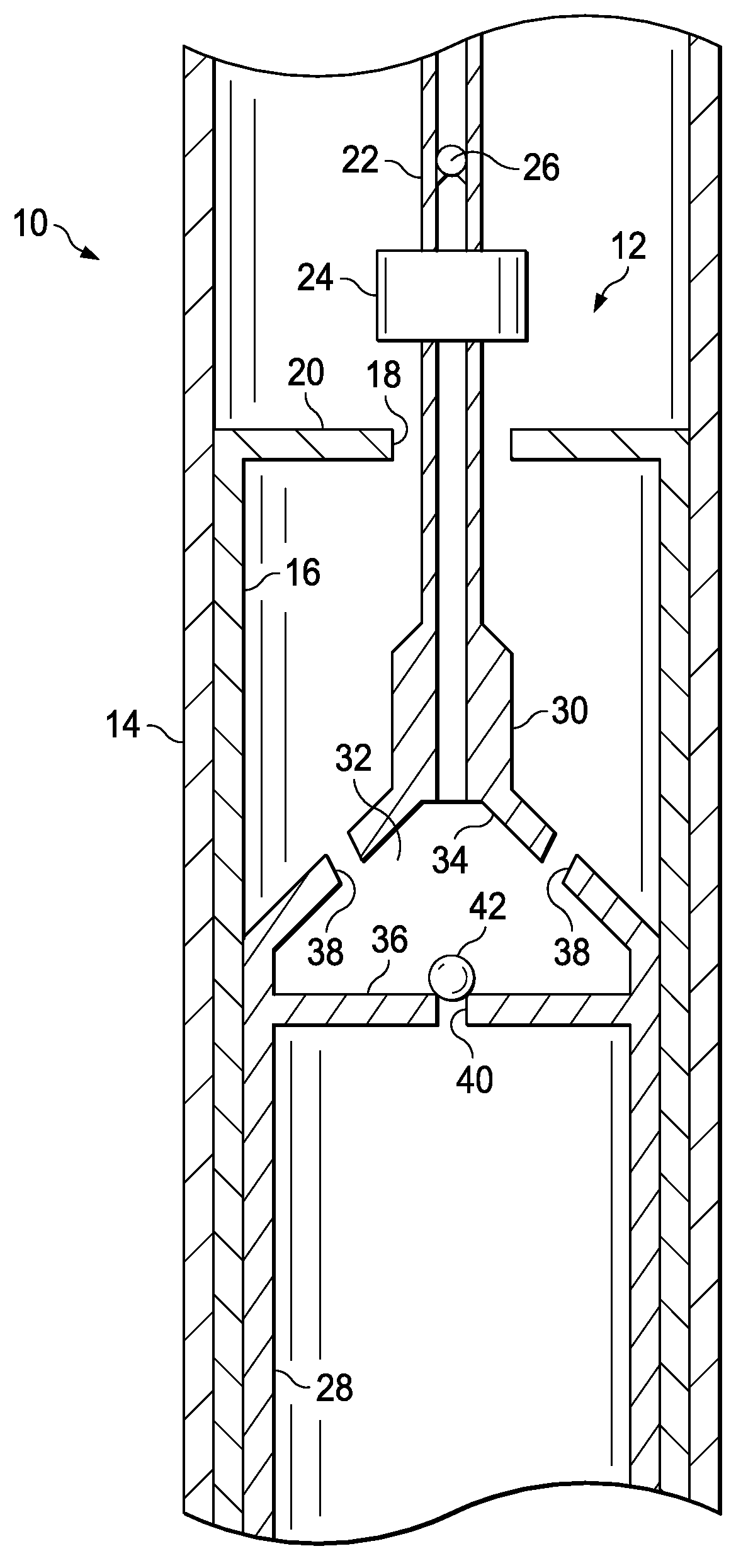
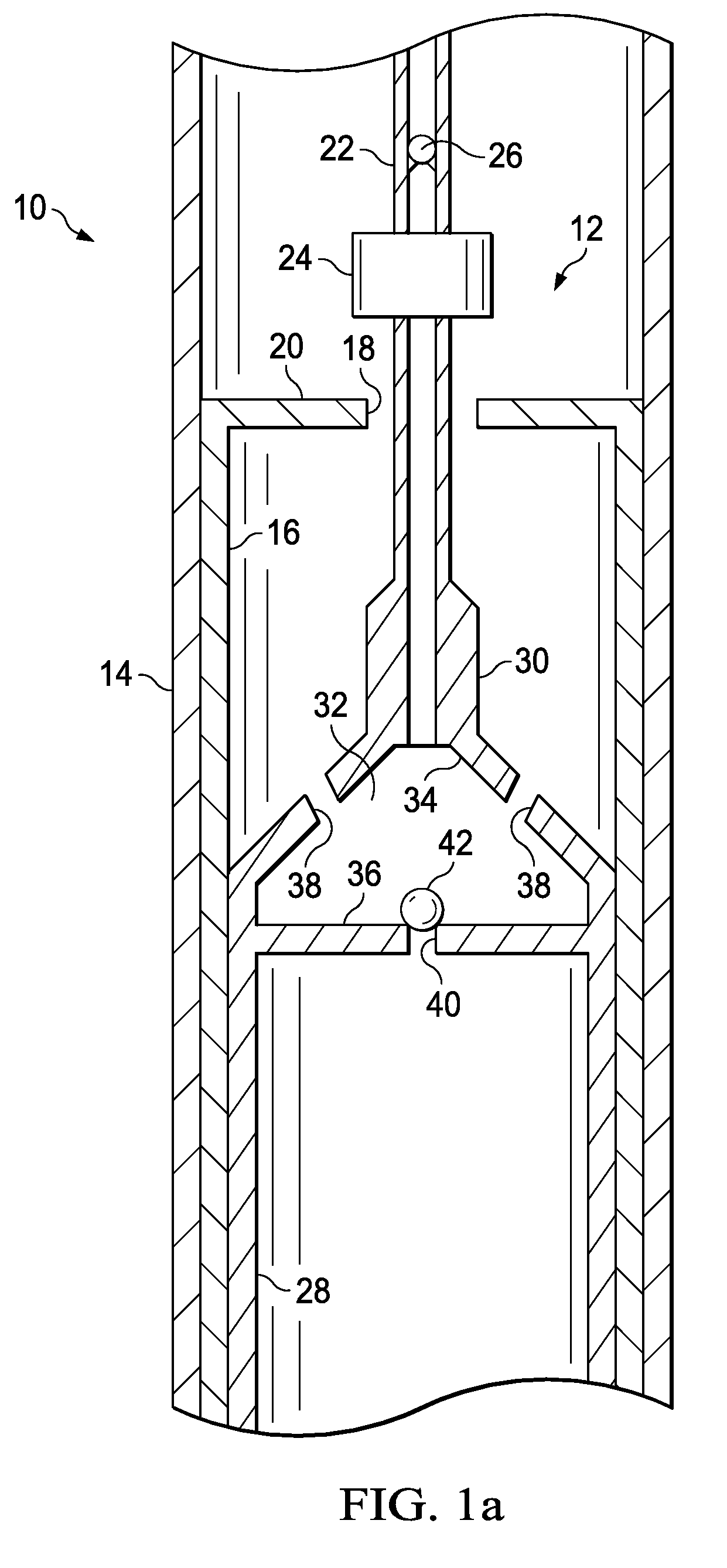
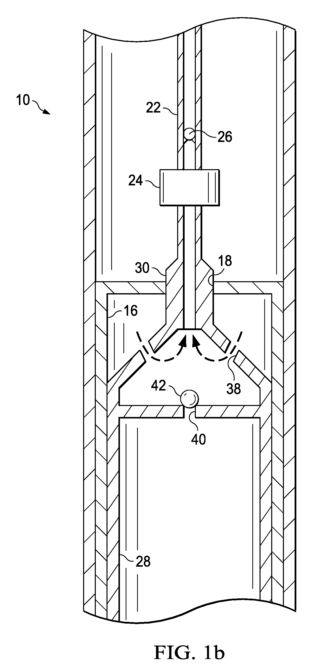
[0022]Referring now to FIGS. 1a-c, well 10 is shown utilizing a first embodiment 12 of a reciprocating pump for efficiently pumping both gas and liquids. Well 10 includes well casing 14. Outer barrel 16 is secured to an inside surface of casing 14. Although this description utilizes the term “well case” or “casing” throughout, it should be understood that casing refers not only to well casing as the term is typically understood in the art, but also to any large tubing within which the pump of the invention may be deployed. Outer barrel 16 has an upper...


PUM


Abstract

A pump for efficiently producing gas in wells having some liquids. The pump may be driven by a walking beam or horsehead pump. The pump of the invention produces gases and liquids separately. Gases may be produced up the annulus between the casing and hollow sucker rods. A plunger seals the opening in the cage during downstroke. Gases and liquids are trapped in the cage above an inner barrel. Liquids are forced up the hollow sucker rod where they are retained by a one-way valve. On the upstroke, the one-way valve seats and gases are forced out of the cage and up the annulus. Gases are, therefore, produced up the annulus and liquids are produced up the drill string. In another embodiment, liquids are retained in a trap and are produced up hollow sucker rods, while gases are produced up the annulus between the hollow sucker rods and the casing.

Description

CROSS REFERENCE TO RELATED APPLICATIONS[0001]This application claims the benefit of U.S. Provisional Patent Application No. 60 / 781,857, filed Mar. 13, 2006, entitled “Reciprocal Pump for Gas and Liquids,” which application is incorporated herein by reference.FIELD OF THE INVENTION[0002]A pump that efficiently produces gas in wells having some liquids. More particularly, the pump of the invention is a reciprocating pump that produces gases and liquids separately.BACKGROUND OF THE INVENTION[0003]As energy needs become more pressing and the price of natural gas rises, it will become economically feasible and desirable to conserve and utilize natural gas from oil wells, including substantially depleted oil wells. One problem with wells that produce gas and some liquids is that when liquids accumulate in pumps designed to produce gas, the liquids put a heavy load on the pumps.SUMMARY[0004]Therefore, it is desirable to provide a pump that is designed to efficiently produce gas in wells ha...

Claims


Application Information

Patent Timeline
Patent Type & Authority Patents(United States)
IPC IPC(8): F04B39/10
CPCF04B47/022
Inventor LEA, JR., JAMES F.
Owner LEA JR JAMES F
Why Eureka
Try Eureka