Apparatus for Performing Body Exercises Having Pivotally Mounted Stabilizers

Inactive Publication Date: 2013-08-29
ROCHFORD TIMOTHY S
View PDF8 Cites 30 Cited by
  • Summary
  • Abstract
  • Description
  • Claims
  • Application Information

AI Technical Summary

Benefits of technology

[0012]In a further embodiment of the present invention, the base stabilizer legs are pivotally or rotatably mounted to the corners of the base plate to provide directional stability for different exercises and difference exercise situations.
[0013]The present invention, due to numerous anchor points for the elastic tubing, provides the capa

Problems solved by technology

It is well recognized, however, that these simple exercises affect only a limited number of muscles in a person's body.
They are not d

Method used


Image

  • Apparatus for Performing Body Exercises Having Pivotally Mounted Stabilizers
  • Apparatus for Performing Body Exercises Having Pivotally Mounted Stabilizers
  • Apparatus for Performing Body Exercises Having Pivotally Mounted Stabilizers

Examples


Embodiment Construction

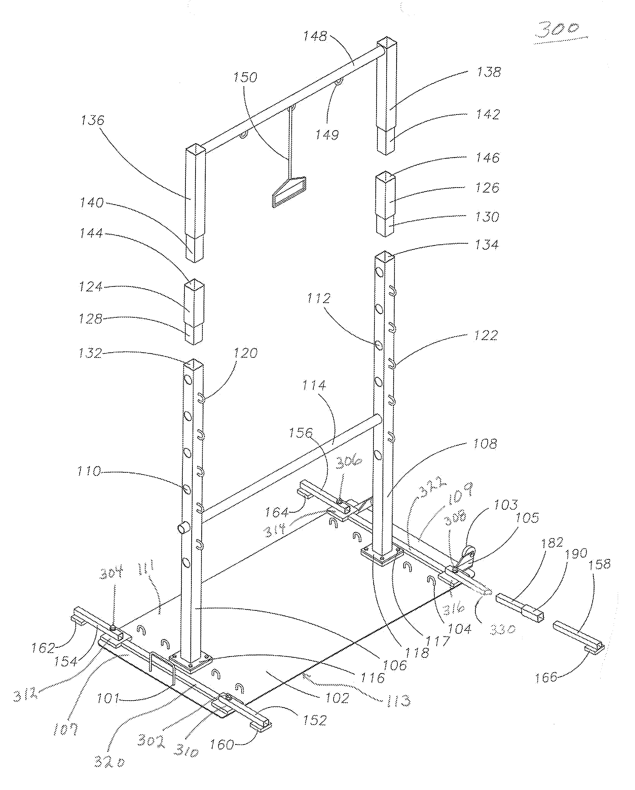
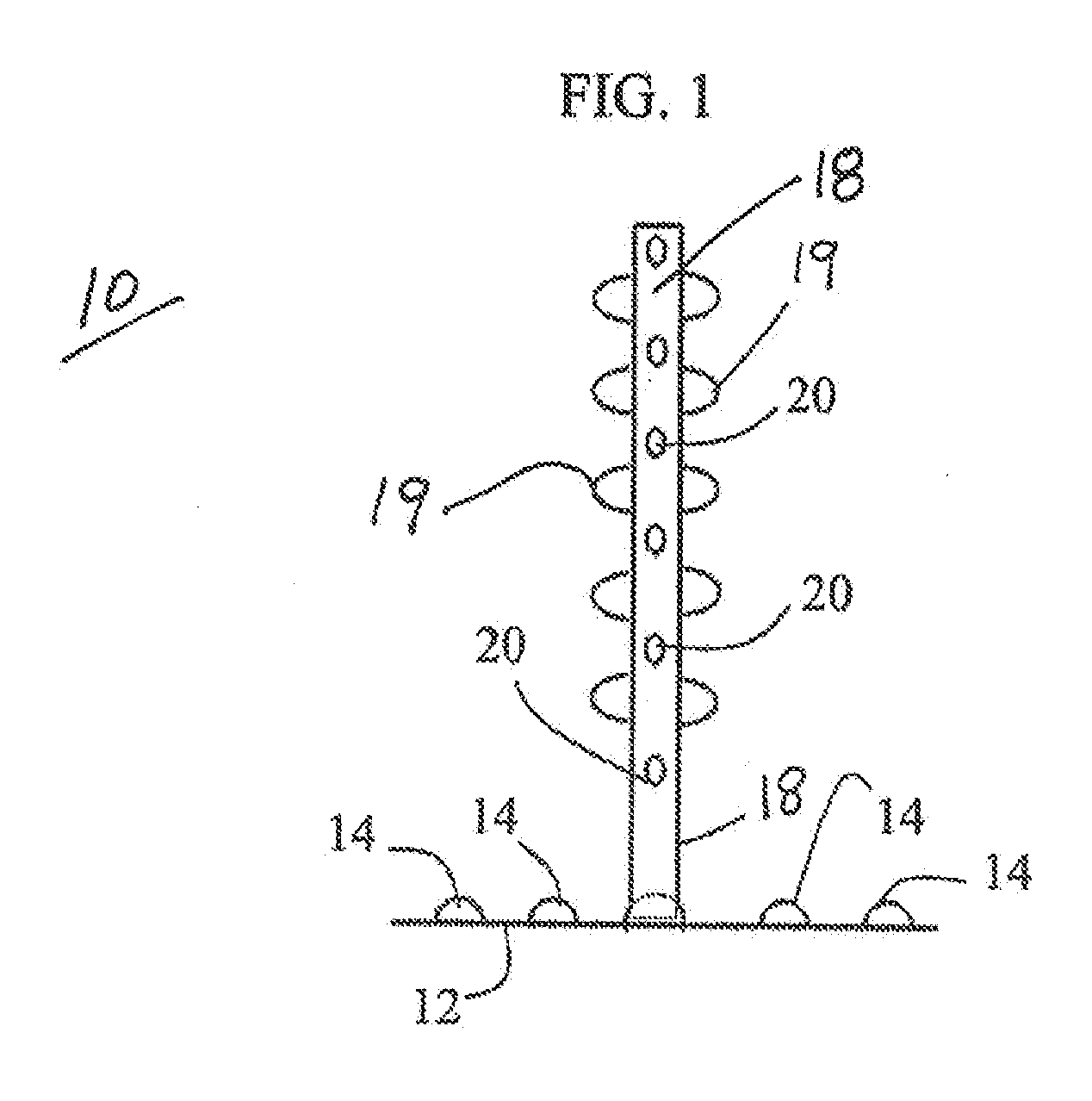
[0023]FIG. 1 illustrates an exercise apparatus 10 configured in accordance with a first embodiment of the present invention. The exercise apparatus 10 is portable and has multiple purposes and uses. The exercise apparatus 10 enables a user to perform body exercises such as push-ups, pull-ups, dips, and the like. The exercise apparatus 10 includes a stable, flat rectangular-type base 12 that has several rigidly attached arch-shaped rods or bars 14 that provide anchor sites for stretch cords. Two vertical towers 18 are rigidly attached to the base 12 by welding and / or bolts. The vertical towers 18 are spaced apart on the base 12 so that enough room is provided for an individual to execute certain exercises while being positioned directly between the vertical towers 18. Each vertical tower 18 has holes 20 that are aligned with holes in the opposite vertical tower 18 through which a round straight cross bar can be inserted to create a level bridge from one vertical tower 18 to the other...


PUM


Abstract

Exercise apparatus having vertical towers rigidly attached to a base plate, including tower extensions that slide inside the tops of the vertical towers to increase their height, and further including base stabilizer leg extensions connected to the base plate to further stabilize the apparatus due to increased height. Base stabilizer mounts are secured to the top of the base plate for receiving base stabilizer legs that extend from the base plate to provide additional stability to the exercise apparatus during operation. Base stabilizer leg extensions can be included to extend the length of the base stabilizer legs. Each of the base stabilizer mounts are aligned along different geometric lines, and do not share any common geometric lines. Stabilizer arms also can be pivotally mounted to the corners of the base plate to provide additional directional stability for the exercise apparatus.

Description

REFERENCE TO RELATED APPLICATIONS[0001]This patent application is a continuation-in-part (CIP) of U.S. patent application having Ser. No. 13 / 035,102 filed on Feb. 25, 2011, and published on Jun. 23, 2011, with publication number 2011 / 0152046, which is a continuation-in-part (CIP) of U.S. patent application having Ser. No. 12 / 541,929, filed on Aug. 15, 2009, and issued as U.S. Pat. No. 7,931,575, on Apr. 26, 2011, which claims priority to U.S. provisional patent application having Ser. No. 61 / 089,530, filed on Aug. 16, 2008.[0002]U.S. Pat. No. 7,931,575 and U.S. patent applications having Ser. Nos. 13 / 035,102 and 61 / 089,530, all previously referenced immediately above, all are hereby incorporated by reference in their entirety into this current patent application.BACKGROUND OF THE INVENTION[0003]1. Field of the Invention[0004]This invention relates to an apparatus for physical exercise, and more particularly, to a self-contained, exercise apparatus for use by an individual for perfor...

Claims


Application Information

Patent Timeline
IPC IPC(8): A63B1/00A63B21/04
CPCA63B1/00A63B21/0442A63B21/04A63B2225/093A63B21/16A63B23/1218A63B2071/025A63B21/0552
Inventor ROCHFORD, TIMOTHY S.
Owner ROCHFORD TIMOTHY S
Why Eureka
Try Eureka