Projection lens and projection device

a projection device and projection lens technology, applied in the field of optical devices, can solve the problems of poor image projection quality and large influence on the quality of the image frame, and achieve the effect of high imaging quality

Active Publication Date: 2013-09-05
YOUNG OPTICS
View PDF19 Cites 41 Cited by
  • Summary
  • Abstract
  • Description
  • Claims
  • Application Information

AI Technical Summary

Benefits of technology

[0009]The invention is also directed to a projection device with high imaging quality by using the above-mentioned projection lens.

Problems solved by technology

Therefore, the quality of the image frame is largely affected by the quality of the projection lens.
However, the wide-angle projection lens known in the art will produce a variety of aberrations such as distortion or field curvature, and makes the quality of the image projected by the projection device poor.

Method used


Image

  • Projection lens and projection device
  • Projection lens and projection device
  • Projection lens and projection device

Examples


Embodiment Construction

[0037]The above-mentioned or other relevant technical principles and the features and effects thereof are clearly depicted together with the accompanying drawings in the following depicted embodiments. Note that some of expression words hereinafter regarding direction or orientation, such as ‘up’, ‘down’, ‘front’, ‘behind’, ‘left’, ‘right’, and the like, are to describe, not to limit, the invention.

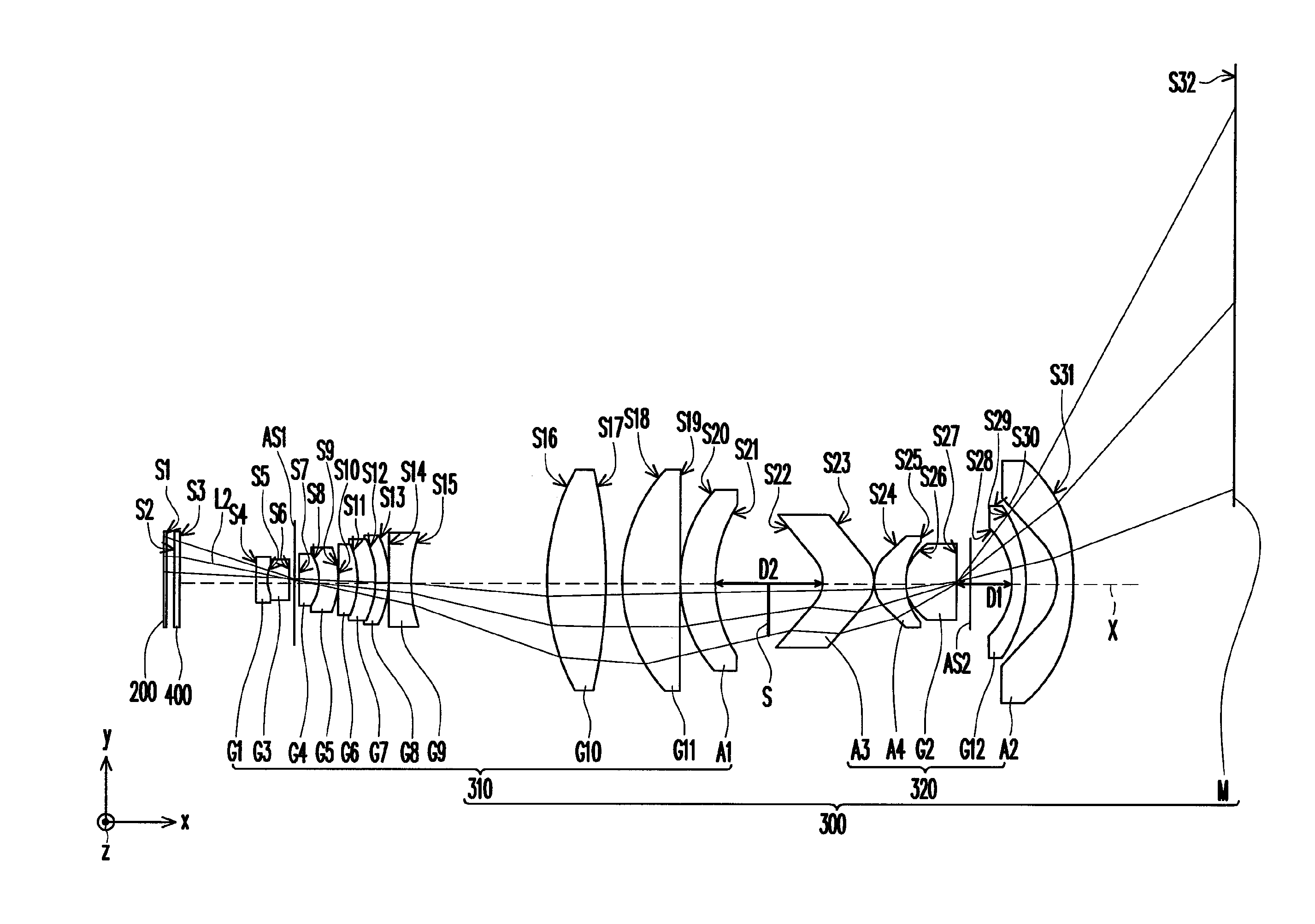
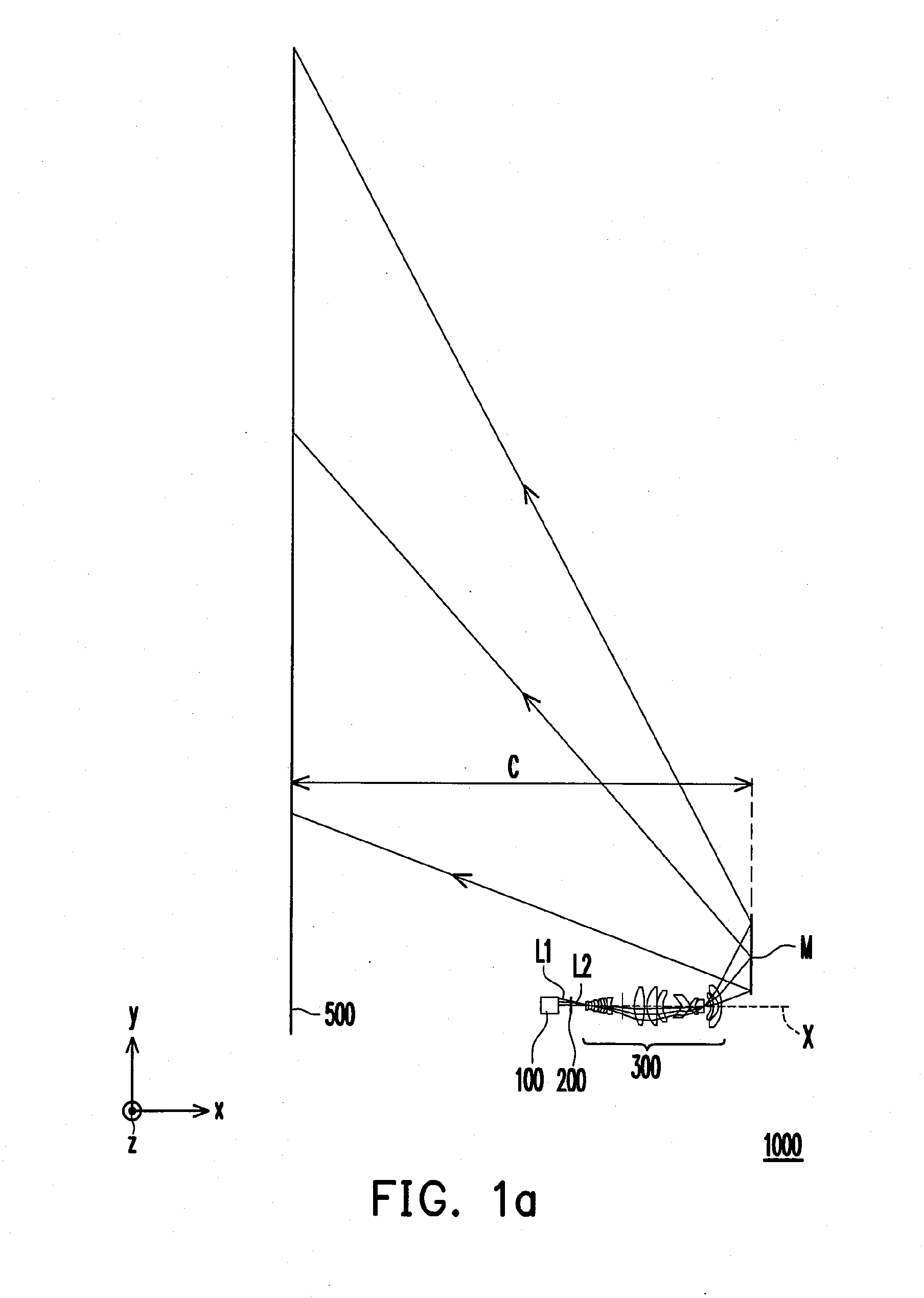
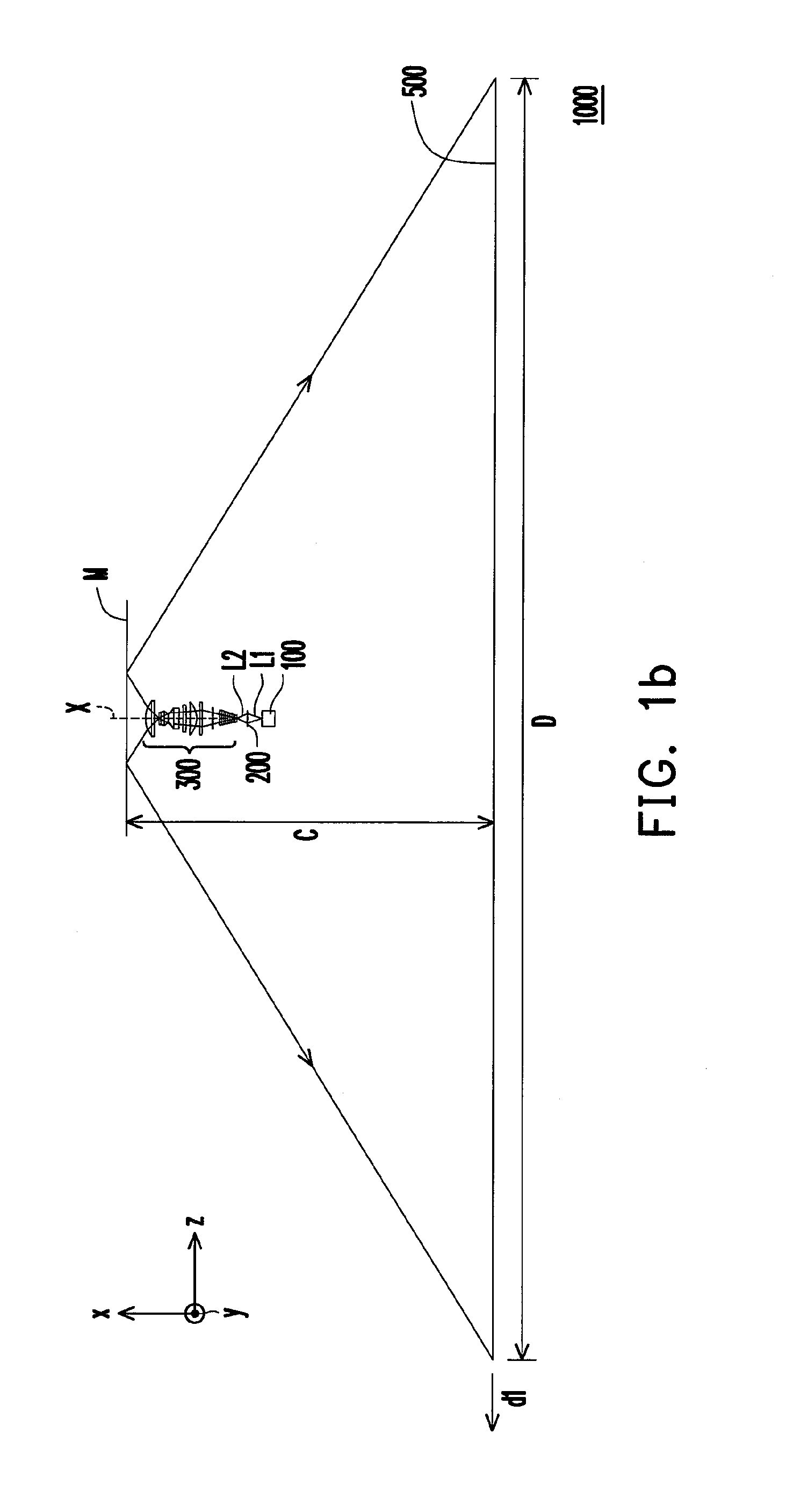
[0038]FIG. 1a is a schematic diagram of a projection device according to an embodiment of the invention and FIG. 2 is a diagram showing the light valve, the projection lens and planar reflector in FIG. 1a. Referring to FIG. 1a, a projection device 1000 of the embodiment includes an illumination unit 100, a light valve 200, a projection lens 300 and a planar reflector M. The illumination unit 100 is for providing an illumination beam L1. The light valve 200 is disposed on the transmission path of the illumination beam L1 to convert the illumination beam L1 into an image beam L2. The projec...


PUM


Abstract

A projection lens provided is for projecting an image beam. The projection lens is disposed on a transmission path of the image beam and includes a first group of lenses and a second group of lenses. The first group of lenses includes a first spherical lens and a first aspheric lens. After the image beam passes through the first group of lenses, an intermediate image is formed between the first group of lenses and the second group of lenses, in which the first aspheric lens is the lens in the first group of lenses closest to the second group of lenses. A projection device using the projection lens is also provided. The projection device further includes a planar reflector on the transmission path of the image beam.

Description

CROSS-REFERENCE TO RELATED APPLICATION[0001]This application claims the priority benefit of China application serial no. 201210052795.1, filed on Mar. 2, 2012. The entirety of the above-mentioned patent application is hereby incorporated by reference herein and made a part of this specification.BACKGROUND OF THE INVENTION[0002]1. Field of the Invention[0003]The invention generally relates to an optical device, and more particularly, to a projection lens with high imaging quality and a projection device using the projection lens.[0004]2. Description of Related Art[0005]Among many types of display devices, the projection device features a smaller device volume but producing a large-size image frame with an area several times of the surface area thereof, so that the projection device in the display field has un-replaced advantage. The projection device projects an image beam converted by a light valve through a projection lens onto a screen. Therefore, the quality of the image frame is...

Claims


Application Information

Patent Timeline
Patent Type & Authority Applications(United States)
IPC IPC(8): G02B3/02G03B21/14
CPCG02B13/18G02B17/08G02B13/16G03B21/28G02B9/64G03B21/147
Inventor LIN, HSIN-HUNGCHEN, YI-HSUEHCHEN, CHAO-SHUN
Owner YOUNG OPTICS
Why Eureka
Try Eureka