Display assembly

a technology for display panels and components, applied in the field of display panels, can solve problems such as performance limitations in conventional examples of display panels

Active Publication Date: 2013-09-12
BAE SYSTEMS PLC
View PDF14 Cites 120 Cited by
  • Summary
  • Abstract
  • Description
  • Claims
  • Application Information

AI Technical Summary

Problems solved by technology

Conventional examples of these displays have performance limitations that arise from a trade-off between providing as wide a fi

Method used


Image

  • Display assembly
  • Display assembly
  • Display assembly

Examples


Embodiment Construction

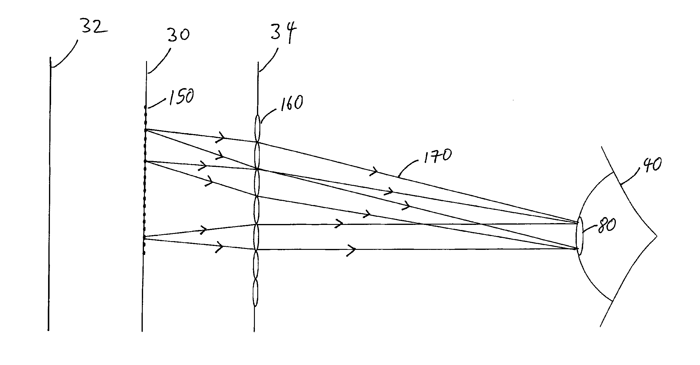
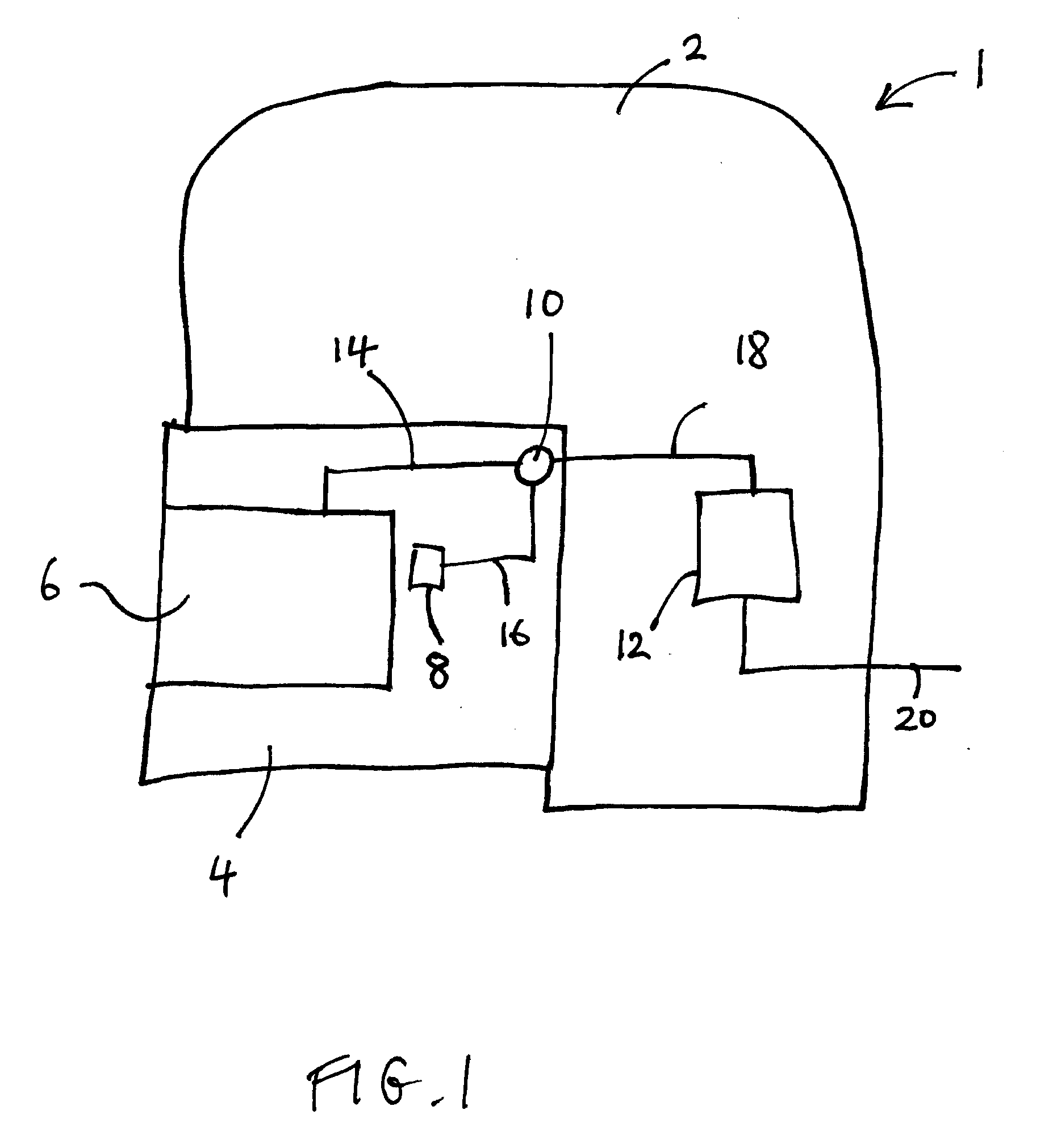
[0034]FIG. 1 is a schematic illustration of a first embodiment of a helmet assembly 1.

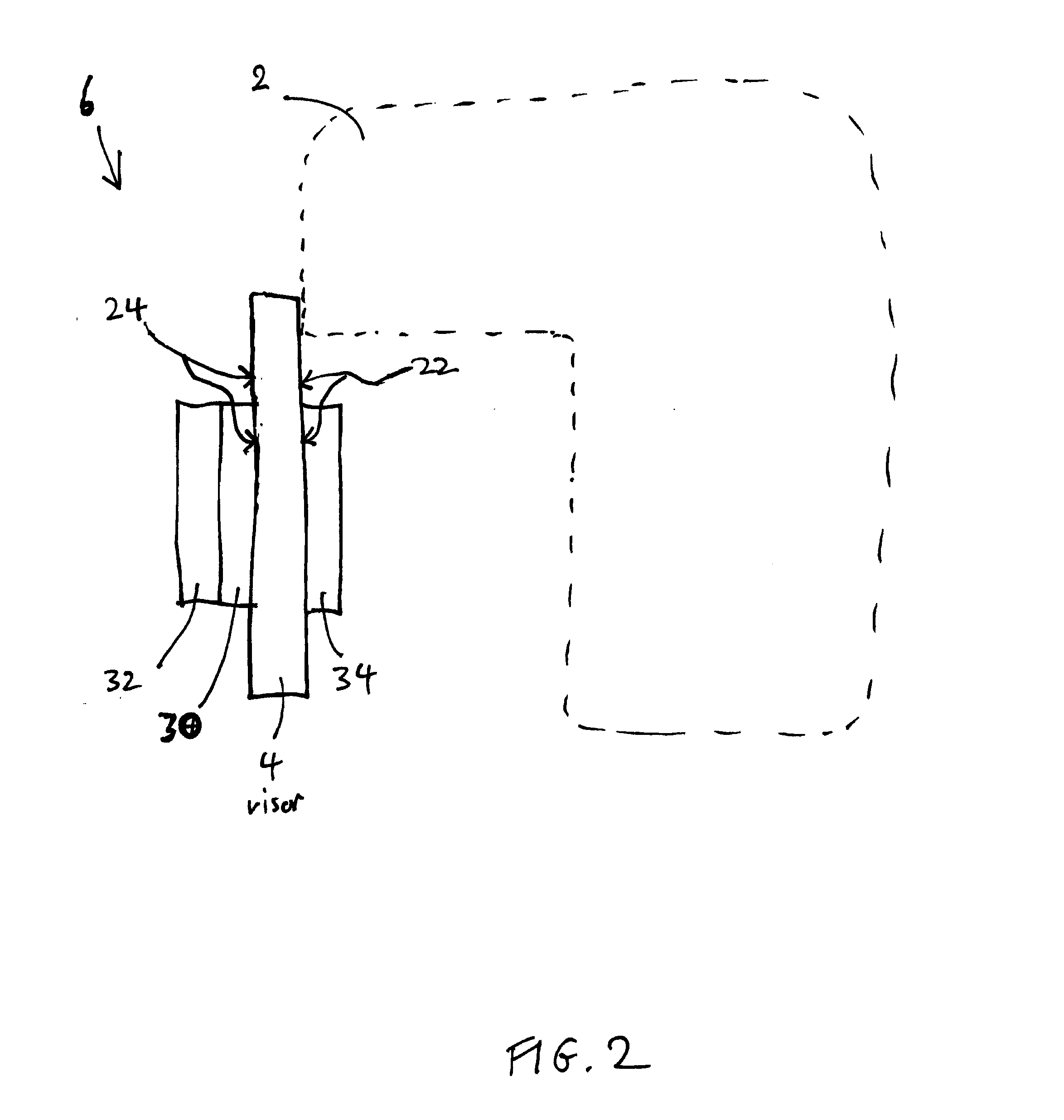
[0035]The helmet assembly 1 comprises a helmet body 2, a visor 4, a transparent display assembly 6, a pupil tracker 8, a connector 10, and a controller 12. The transparent display assembly 6 is electrically connected to the connector 10 by a link, hereinafter referred to as the display link 14. The pupil tracker 8 is electrically connected to the connector 10 by a further link, hereinafter referred to as the pupil tracker link. The connector 10 is electrically connected to the controller 12 by a further link, hereinafter referred to as the controller link 18. The controller 12 is electrically connected to electronics (not shown) external to the helmet assembly 1 by a further link, hereinafter referred to as the external link 20.

[0036]In this embodiment the helmet assembly 1 is an aviation helmet assembly. The helmet body 2 is a conventional helmet body of an aviation helmet except where described o...


PUM


Abstract

A display assembly, comprising: a display device (30); a microlens array (34); and an eye tracker (8), for example a pupil tracker (8), and/or a head tracker; wherein plural pixels (150) or sub-pixels of the display device (30) are provided for each microlens (160) of the microlens array (34). The display may be adapted such that only certain pixels/sub-pixels (150) are activated/selected for any particular determined pupil/eye/head position, for example such that for each microlens (160), only one respective pixel/sub-pixel (150) is activated/selected for any particular determined pupil/eye/head position. The display device (30) may be a transparent display device (30), the microlens array (34) may be a switchable microlens array (34), and the display assembly may further comprise a light blocking device (32) that is switchable between a substantially light blocking state and a substantially light passing state.

Description

FIELD OF THE INVENTION[0001]The present invention relates to displays. The present invention relates in particular to, but is not limited to, head-up displays, for example head-up displays in aviation helmets.BACKGROUND[0002]Many head mounted displays offer a fully immersive visual environment, which may be termed virtual reality display, i.e. the user does not observe any outside scene and instead only observes images provided by the display. Providing displays in helmets, e.g. head-up displays in aviation helmets, is also known. These displays typically provide a display imaged at infinity superimposed onto the outside world image. Conventional examples of these displays have performance limitations that arise from a trade-off between providing as wide a field of view as possible with the increase in the weight of the projection system required for increasing width of field of view. In relation to certain helmets, e.g. helmets for soldiers, it has been proposed to provide transpar...

Claims


Application Information

Patent Timeline
IPC IPC(8): G02B27/00
CPCG02B3/0006G02B26/004G02B2027/0187G02B27/017G02B27/0093
Inventor GRIFFITH, MICHAEL STEWART
Owner BAE SYSTEMS PLC
Why Eureka
Try Eureka