

Optical MEMS scanning micro-mirror with speckle reduction
a technology of optical mems and micro-mirror, applied in optics, instruments, projectors, etc., can solve the problems of affecting the visual comfort of the viewer, affecting the image quality, and creating constructive and destructive interference, so as to reduce or suppress the speckle and avoid the parasitic reflection of ligh
- Summary
- Abstract
- Description
- Claims
- Application Information
AI Technical Summary
Benefits of technology
Problems solved by technology
Method used
Image

Examples
Embodiment Construction
[0061]For clarity, as is generally the case in representation of microsystems, the various figures are not drawn to scale.
[0062]The present invention is based on studies performed by the inventors into the origins of parasitic light reflection onto transparent or semi-transparent surfaces for scanning and projection purposes.
[0063]The invention proposes to change the geometry of the protection window to avoid parasitic reflection, provide an anti-speckle effect, while keeping the assembly simplicity of such window with other components.
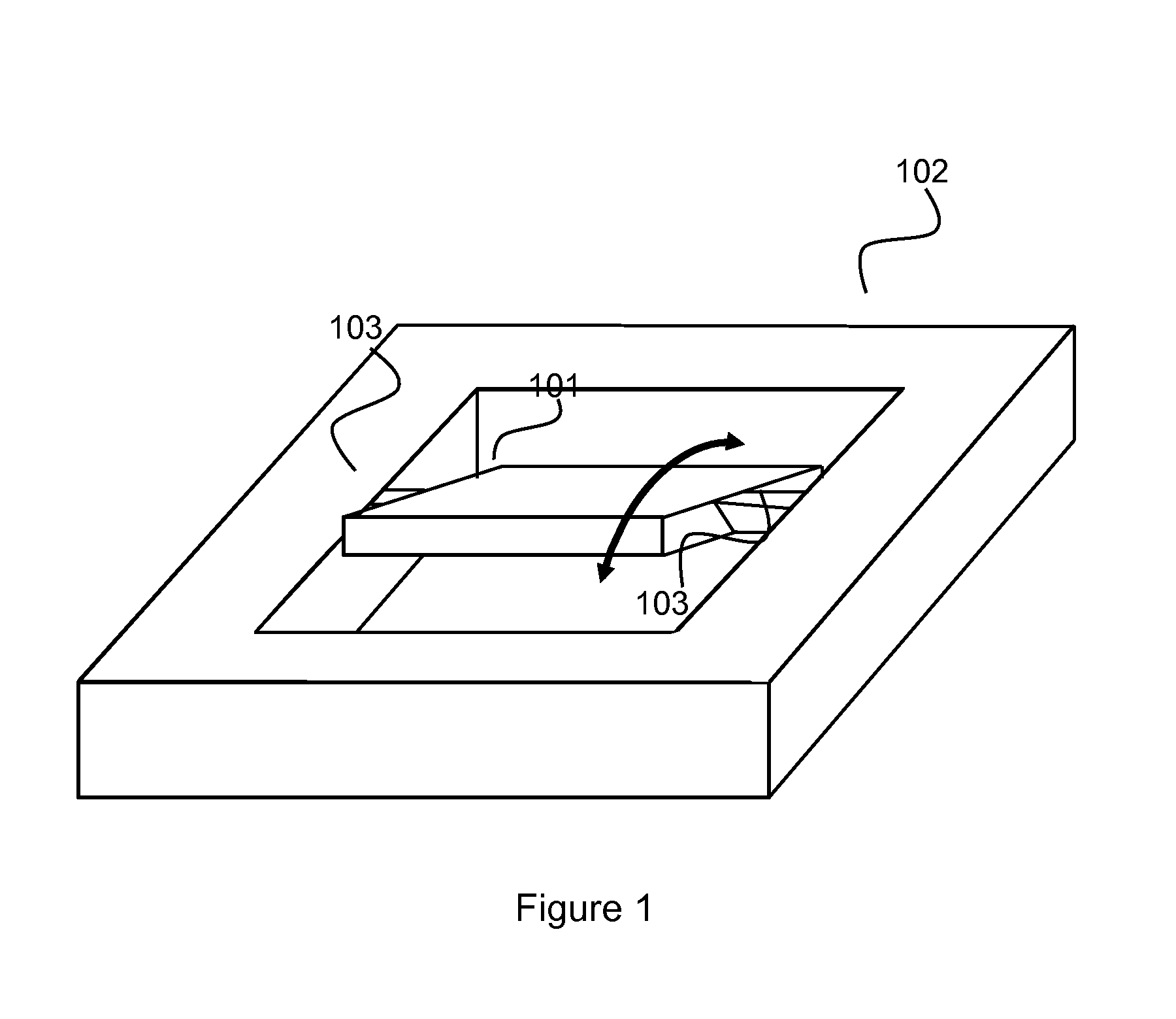
[0064]FIG. 1 presents a typical rectangular MEMS moving micro-mirror 101, anchored to a fix body 102 by two beams 103, and deflected along its central axis.
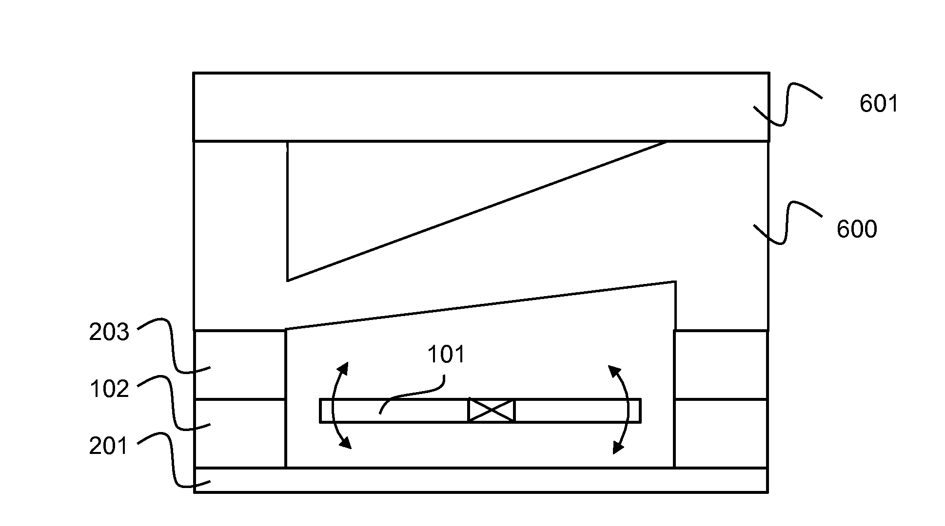
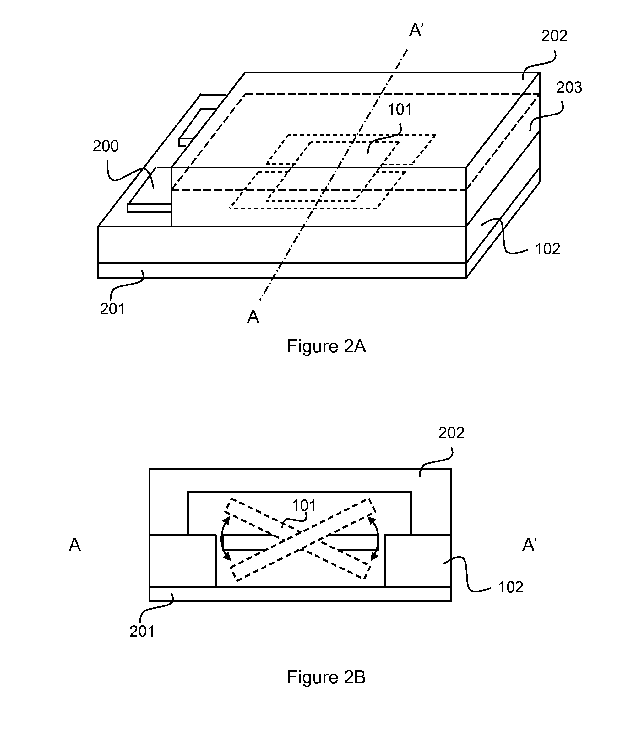
[0065]An example of known type packaged MEMS mirror is presented in FIG. 2A and FIG. 2B, where the MEMS mirror 101 is protected by transparent or semi-transparent surfaces 201 and 202 as the incoming light can either come from one side or from two sides of the mirror surfaces.
[0066]FIG. 3 presents ...
PUM
 Abstract
Description
Claims
Application Information