

Protection module for data transmission connector
- Summary
- Abstract
- Description
- Claims
- Application Information
AI Technical Summary
Benefits of technology
Problems solved by technology
Method used
Image

Examples
Embodiment Construction
[0014]The present invention will now be described with a preferred embodiment thereof and with reference to the accompanying drawings.
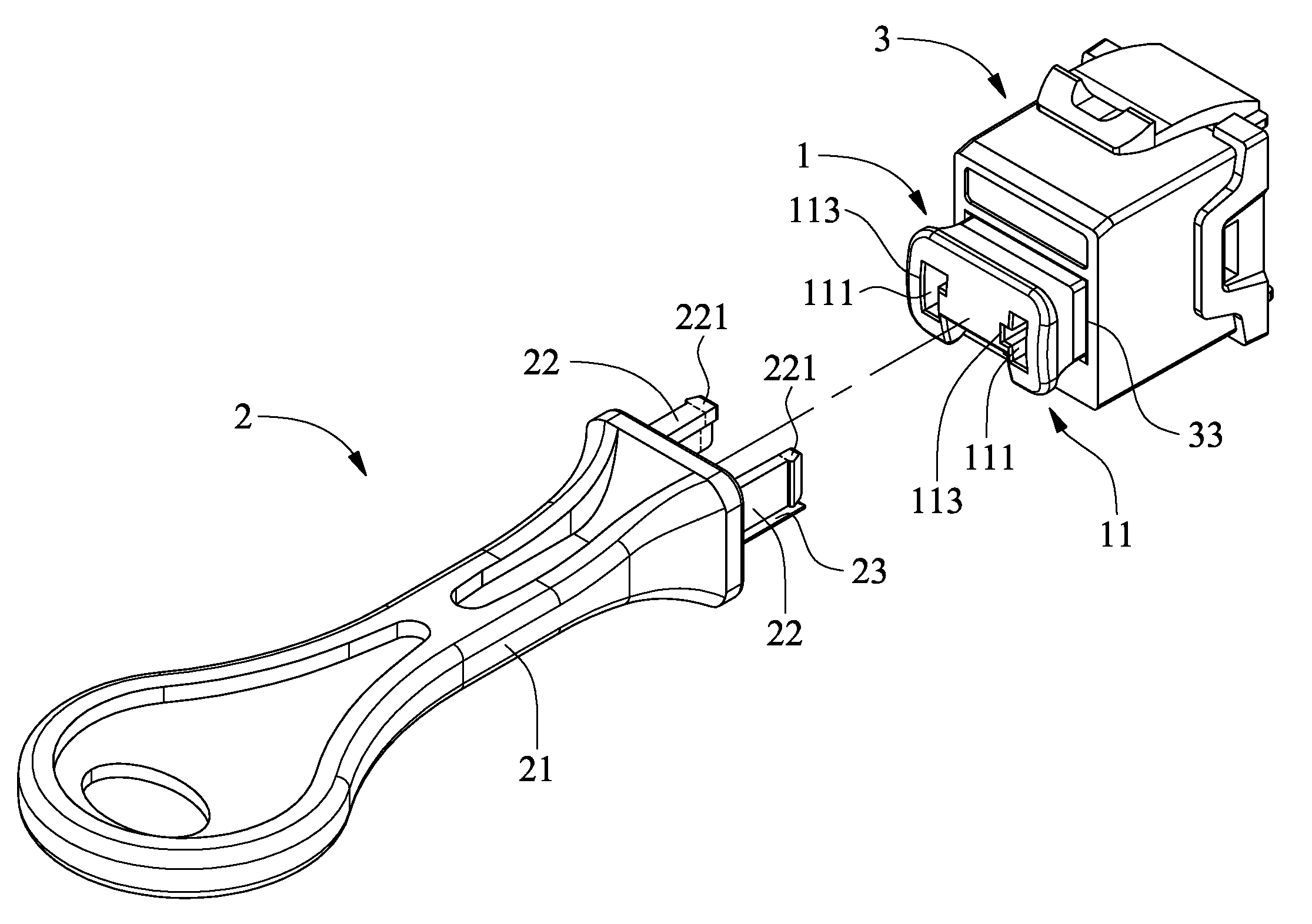
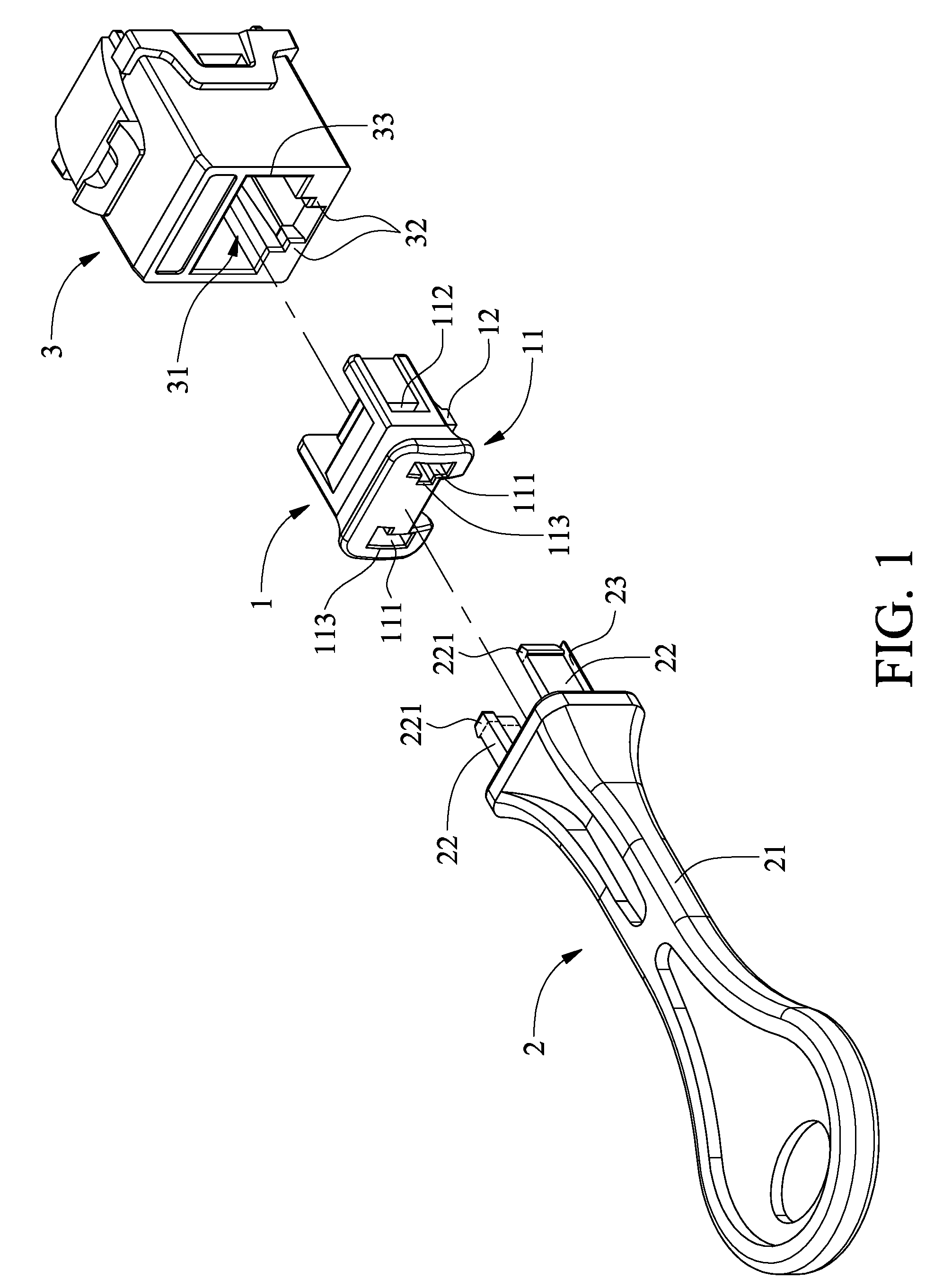
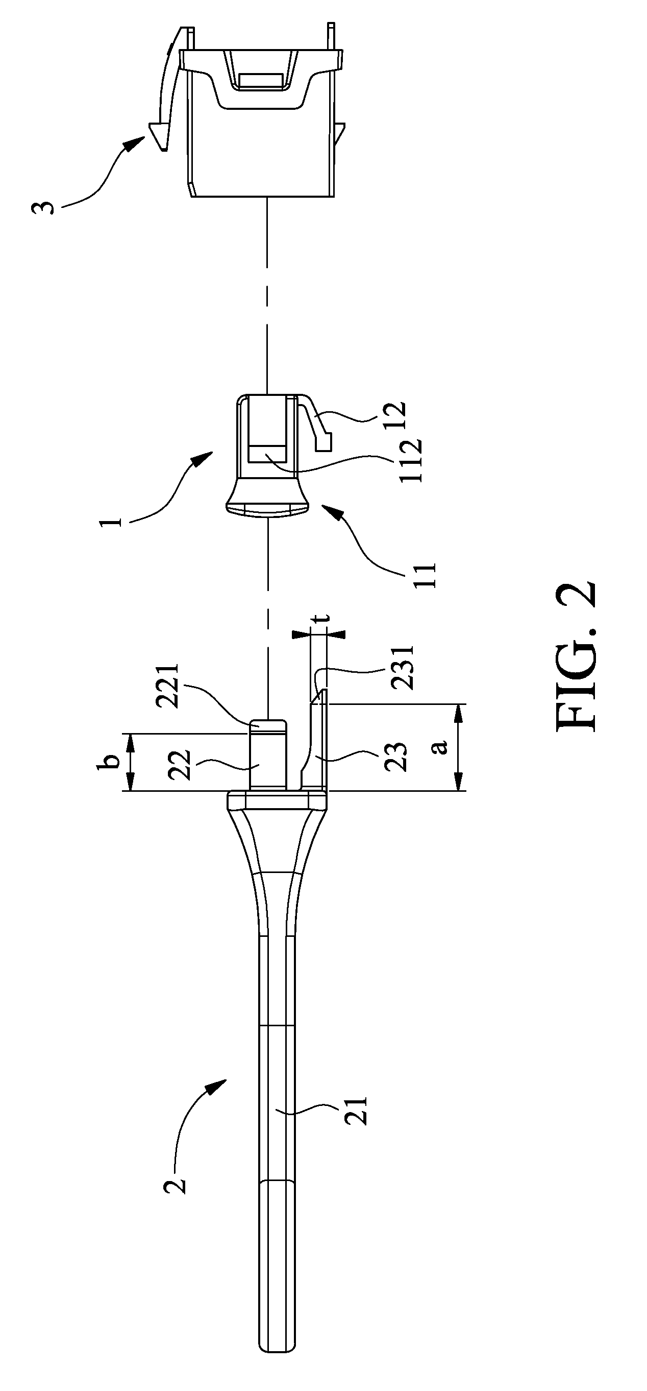
[0015]Please refer to FIGS. 1 and 2 that are exploded perspective and side views, respectively, of a protection module for data transmission connector according to an embodiment of the present invention. As shown, the protection module of the present invention includes a protective cover 1 and a cover removing tool 2; and a data transmission connector 3 to be protected by the protection module of the present invention includes a socket 31 and two raised portions 32 located at two lateral sides of an opening 33 of the socket 31 to space from each other. Please also refer to FIGS. 3A to 3C that are front views of the cover removing tool 2, the protective cover 1, and the data transmission connector 3, respectively.
[0016]The protective cover 1 has a first main body 11 and an elastic arm 12. The first main body 11 is provided with at least one engaging sl...
PUM
 Abstract
Description
Claims
Application Information