Coupler with Magnet

a magnet and coupling technology, applied in the field of couplings, can solve the problems of user error, lost operator time, etc., and achieve the effect of safe us

Inactive Publication Date: 2012-09-13
MILLER INT
View PDF2 Cites 3 Cited by
  • Summary
  • Abstract
  • Description
  • Claims
  • Application Information

AI Technical Summary

Benefits of technology

[0057]Preferably a rear surface of the second latching mechanism is stepped in an area thereof, each step defining a location against which a free end of a blocking bar may bear. This is to allow multiple different blocking positions for the blocking bar. This permits the coupler to be used safely on a variety of different accessories, each having different accessory pin centers (distances between the pin centers).

Problems solved by technology

There is also a further problem with couplers of this type—users occasionally use them incorrectly.
There is also an issue with couplers in that with the automated operation, misalignment of elements within the coupler, due to operator shortcuts, can lead to errors in either or both of the coupling and decoupling procedures, whereby the coupling or decoupling procedure will not complete successfully, thereby leading to repeated attempts at coupling / decoupling, and thus lost operator time.

Method used


Image

  • Coupler with Magnet
  • Coupler with Magnet
  • Coupler with Magnet

Examples


Embodiment Construction

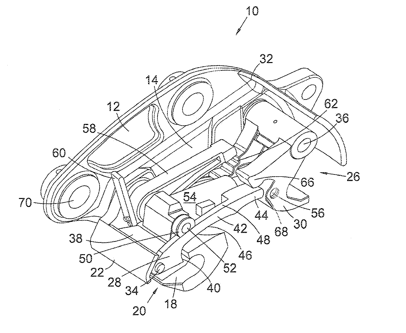
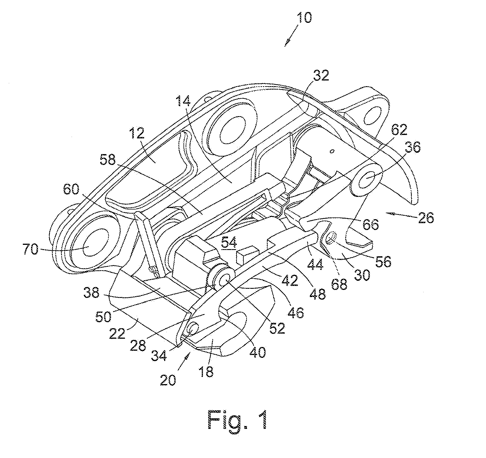
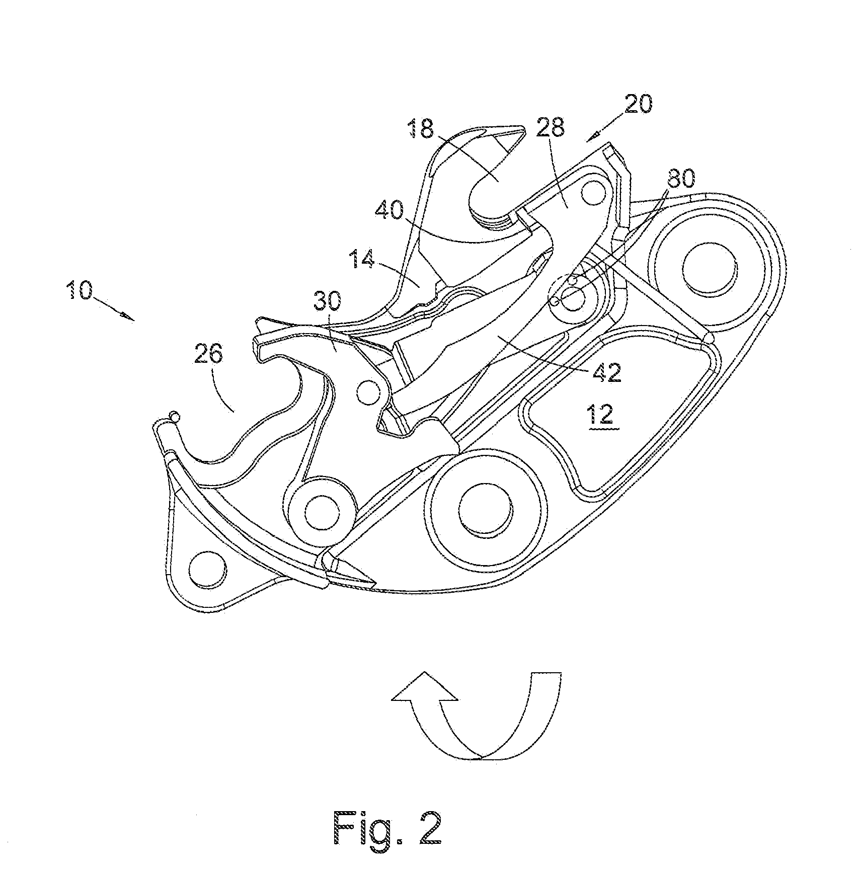
[0087]Referring first of all to FIG. 1, there is shown a coupler 10 having a first half 12 for mounting onto an end of an excavator arm of an excavator (not shown) and a bottom half 14 in which is mounted the working mechanisms of the coupler 10. In this illustrated embodiment, the top half 12 of the coupler 10 is mounted onto the excavator arm of the excavator by a pair of accessory pins (not shown), as is conventional for excavator couplers and accessories. Other known mechanisms for mounting couplers to an excavator arm can also be used instead, by making appropriate changes to the top half of the coupler.

[0088]The bottom half 14 of the coupler accommodates the working mechanism of the coupler 10. It consists of a first jaw 18 having an opening 20 at or near the front 22 of the coupler 10. That opening faces the forwards direction relative to the coupler. The first jaw 18 is for receiving a first accessory pin or accessory attachment member of an accessory, such as an excavator b...


PUM


Abstract

A coupler includes first and second attachment pin jaws. A first latching mechanism is associated with the first jaw. The first latching mechanism has an arm connected to and extending away from a latching member. A second latching mechanism is associated with the jaw. The first and second latching mechanisms are adapted to latch the first and second attachment pins of an accessory in or on the first jaw and the second jaw, respectively. The second latching mechanism is powered for movement between a latching position and a non-latching position. The first latching mechanism is operatively connected to, or connectable with, the second latching mechanism to allow it to selectively operate the first latching mechanism between latching and non-latching positions by means of a groove or flange or finger on the second latching mechanism. A magnet is provided to ensure a correct disengagement of the first latch latching mechanism.

Description

CROSS-REFERENCE TO RELATED APPLICATIONS[0001]The present application claims priority to UK Patent Application No. 1104041.7 filed Mar. 9, 2011, the entire disclosure of which is expressly incorporated by reference.STATEMENT REGARDING FEDERALLY SPONSORED RESEARCH OR DEVELOPMENT[0002]Not applicable.REFERENCE TO A “SEQUENCE LISTING”[0003]Not applicable.BACKGROUND OF THE INVENTION[0004]1. Field of the Invention[0005]The present invention relates to a coupler for attaching an accessory, such an excavator bucket, to an excavator arm of an excavator. In particular, it relates to a fully automatic coupler for attachment, at its top half, to an excavator arm, and having, in its bottom half, two jaws and two latches for selectively securing (or releasing) two attachment pins of an accessory in (or from) the jaws of the coupler.[0006]2. Description of Related Art[0007]Not applicable.BRIEF SUMMARY OF THE INVENTION[0008]Many different couplers for attaching accessories to an excavator arm of an ...

Claims


Application Information

Patent Timeline
Patent Type & Authority Applications(United States)
IPC IPC(8): E02F3/36
CPCE02F3/3618E02F3/3631Y10T403/581E02F3/3645E02F3/3663E02F3/364F16B2200/69E02F3/3604E02F3/3609E02F9/24
Inventor REAY, HOWARDMILLER, GARYMILLER, RONALD KEITH
Owner MILLER INT
Why Eureka
Try Eureka