
Nail plate and cable protection sleeve for building framing

a technology of protecting sleeve and nail plate, which is applied in the direction of walls, constructions, building components, etc., can solve the problems of undetected closing of utility conduits, damage to nails or screws, and now largely out of favor

Inactive Publication Date: 2013-09-26
TURNER BRUCE H
View PDF7 Cites 14 Cited by
  • Summary
  • Abstract
  • Description
  • Claims
  • Application Information

AI Technical Summary

Benefits of technology

The present invention provides a sleeve assembly for use in building framing to protect utility conduits. The assembly includes a sleeve and a sleece plate. The sleeve has a hollow trough longitudinally with a circular side section that can be adjusted to fit different sizes of holes in studs. The sleeve can be inserted into the hole in the stud and pressed onto it with the help of the sleece plate which attaches to the stud. The sleeve is designed to provide a secure and adjustable way to protect utility conduits during building construction.

Problems solved by technology

This approach has been widely used in the past but is now largely out of favor because it is felt to unduly undermine stud and wall strength.
Additionally, for reasons that will be discussed presently, this approach undesirably puts utility conduits close to a wall surface, rather than in a wall center furthest away from all such surfaces.
Most walls today are covered by nailing or screwing wall cover material to the studs, thus exposing the conduits passing through the studs to the risk that one of these nails or screws will damage them.
Similarly, once utility conduits are “hidden” within a wall, they are at risk from anything that later penetrates the wall.
Potentially, such penetration can occur anywhere in a wall and all points of a utility conduit are thus seemingly at risk.
As a practical matter, however, such penetration usually is at studs and poses the greatest risk there.
If this hypothetical handy-person lacks foresight, and simply drives their nail into the wall anywhere, the chances are that it will not be driven into a stud and that the mirror will not be well secured.
Unfortunately, if per chance the nail in this scenario is driven into a stud and there encounters a utility conduit, say, an electrical power cable, the stud will tend to hold the cable relatively fixed and this will increase the likelihood that the nail will penetrate it, potentially shorting the conductors and starting a fire.
This solution is quite elaborate and material-intensive.
Unfortunately, all of the presently used approaches to shielding utility conduits have limitations or involve trade-offs.
For example, as noted above, all of the approaches that are specific for use with through-notching are undesirable because through-notching undermines the strength of the studs and ultimately the walls that they are part of.
Granted, the shielding over the through-notch should help protect the conduits within it, but this still brings the rest of the conduits closer to one wall and generally exposes them to possible damage by shorter penetrations.
All of the side-of-stud plate-based approaches, both for use over through-notches and through-holes, also have another inherent limitation.
But this is not necessarily always the case.
Obviously, this possibility is totally foreclosed if a metal side-of-stud plate is used.
This can result in a wall covering having an aesthetically unpleasing buckled or warped appearance.
While flat plates with projections (teeth, prongs, or barbs) are easy to make (see e.g., Williamson's stud shield, discussed above), they also require an undue quantity of material to make.
Firstly, such a plate usually has to have portions extending above and below the through-notch or through-hole being covered for the projections that will be driven into a wooden stud.
Secondly, even when this is not the case (see e.g., Lalancette's plate for use in limited applications and Zastrow et al's adhesive plate), side-of-stud plates need to extend more than the vertical width of the through-notch or diameter of the through-hole to protect against nails or screws driven into a stud adjacent to the plate but at an angle such that utility conduits might still be damaged.
Side-of-stud plate-based approaches are also unsuitable for use after wall covering, e.g., for running new utility conduits in existing construction.
This material-intensive nature of plate-based approaches is not well appreciated in the industry, largely because it has slowly grown in importance and “conventional wisdom” is that plates are fine and their cost is simply one that must be endured.
The point here is that we have slowly grown to use roughly ten-fold as much utility conduit shielding as we once did, and the materials for that and their cost have become substantial.
Nonetheless, the multi-cylinder approach by Nelson and multi-sheath embodiments in accord with Wilkerson's approach are actually not economical with respect to the amount of material they require.
The problem is, however, that Wilkerson's sheaths have no mechanism other than surface friction to retain them in a through-hole, and the greater the degree of taper they have the more likely they are to simply pop back out of a through-hole.
Using ¾″ or 1⅛″ bits will likely produce holes that will not work for 1″ Wilkerson sheaths.
Furthermore, with no significant retaining mechanism, Wilkerson sheaths are not reliably useable with sheet metal type studs.
[Notably, Wilkerson's filing in 1954 pre-dates the significant use of sheet metal studs and this reference does not teach the use of its sheathes in such.]
Similarly, Baillie's dimpled tubes are very economical with respect to material but have other limitations.
Also, even though the first of the patents for this was filed for in 1973, when sheet metal studs where becoming known, Baillie does not teach, and apparently it simply was not contemplated, that its dimpled tubes could be used in sheet metal studs.
Accordingly, the presently most widely used utility conduit protection scheme, plates affixed to stud edges, is uneconomical and has utilitarian limitations.
Similarly, all of the other known plate-based approaches suffer from at least the same problems.
Conversely, present center-of-stud specific approaches are either less economical than possible, also have utilitarian limitations, or both.

Method used


Image

  • Nail plate and cable protection sleeve for building framing
  • Nail plate and cable protection sleeve for building framing
  • Nail plate and cable protection sleeve for building framing

Examples


Embodiment Construction

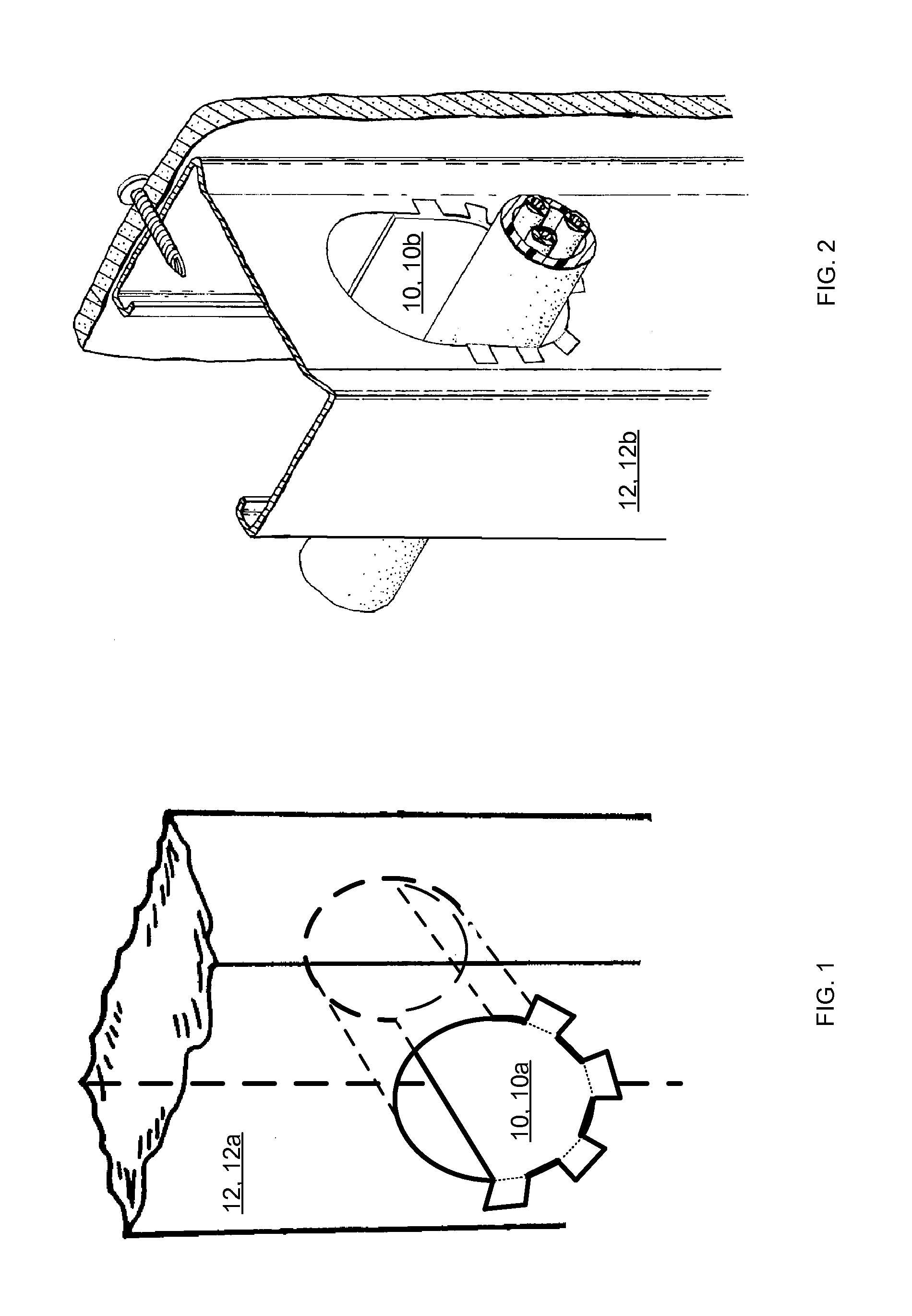
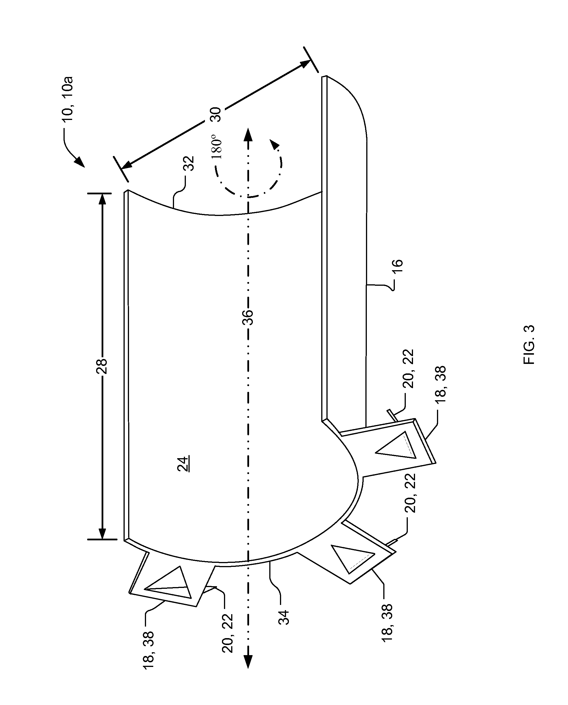
[0050]A preferred embodiment of the present invention is a sleeve assembly for use in building framing to protect utility conduits. As illustrated in the various drawings herein, and particularly in the views of FIGS. 1-4, 10 and 13, preferred embodiments of the invention are depicted by the general reference character 10.

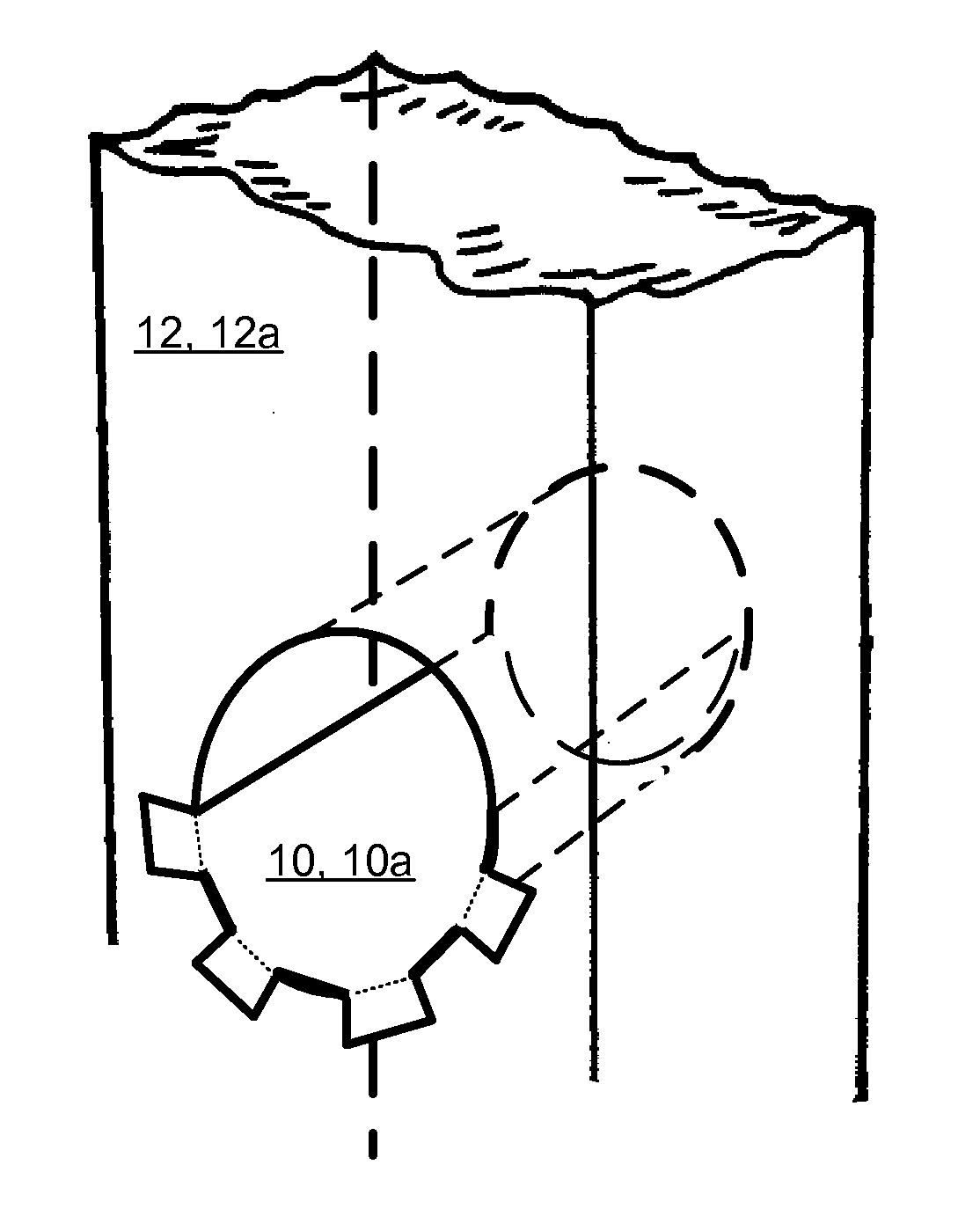
[0051]FIGS. 1-2 depict two embodiments of sleeves 10 in accord with the present invention that are being employed. The sleeves 10 are used with studs 12 and, while reference characters are assigned herein based on the order in which elements and features are first discussed, it should nonetheless be appreciated that the sleeves 10, and their elements, comprise the present invention while the studs 12, and their features, merely comprise work pieces upon or with which the present invention may be employed. To facilitate the following discussion, the sleeve 10 in FIG. 1 is termed a shallow-trough sleeve 10a and the sleeve 10 in FIG. 2 is termed a deep-trough sleeve 1...


PUM


Abstract

An assembly for protecting a utility conduit passing through a hole in a stud used in building construction. A sleeve and a plate are provided. The sleeve has a body forming a hollow trough with a length, a circular side section and a width The circular side section is changeable to adapt to the hole in the stud. The body has opposed inserted and worked end to permit engagement of the sleeve into the hole in the stud. The body portion can include a sleeve fillant within the trough. A stop portion at the worked end of the body stops sleeve insertion a proximate stud. A retention portion then affirmatively retain the sleeve in the hole. The plate has a surface conforming to a stud face, an opening to receive the sleeve, and a mechanism to attach the plate to the stud.

Description

CROSS-REFERENCE TO RELATED APPLICATIONS[0001]This is a continuation-in-part of application Ser. No. 12 / 029,595, filed Feb. 12, 2008, which is a continuation-in-part of application Ser. No. 11 / 308,329, filed Mar. 16, 2006 and issued Jun. 5, 2012 as U.S. Pat. No. 8,191,323, hereby incorporated by reference in their entirety.STATEMENT REGARDING FEDERALLY SPONSORED RESEARCH OR DEVELOPMENT[0002]Not applicable.THE NAMES OF THE PARTIES TO A JOINT RESEARCH AGREEMENT[0003]Not applicable.INCORPORATION-BY-REFERENCE OF MATERIAL SUBMITTED ON A COMPACT DISC[0004]Not applicable.BACKGROUND OF THE INVENTION[0005]1. Technical Field[0006]The present invention relates generally to electrical conductors and insulators, and the apparatus specialized to mounting, protecting, encasing in conduits, and housing insulators, and more particularly to conduits and housings mounted on, in or through the walls of building structures.[0007]2. Background Art[0008]In most types of buildings today framing members, com...

Claims


Application Information

Patent Timeline
Patent Type & Authority Applications(United States)
IPC IPC(8): H02G3/04
CPCE04B2/7457E04B2002/7488E04C3/065H02G3/22H02G3/0481
Inventor TURNER, BRUCE H.
Owner TURNER BRUCE H
Learn More