Pneumatic tire

a technology of pneumatic tires and tires, applied in the field of pneumatic tires, can solve the problems of reducing the contact area of tires, reducing steering stability, and slipping risk, and achieve the effect of excellent on-snow performance and good steering stability

Active Publication Date: 2013-09-26
BRIDGESTONE CORP
View PDF7 Cites 28 Cited by
  • Summary
  • Abstract
  • Description
  • Claims
  • Application Information

AI Technical Summary

Benefits of technology

[0014]According to the present invention, it is possible to provide a pneumatic tire that has excellent on-snow performance while maintaining good steering stability on a dry road surface by providing optimized first circumferential narrow grooves only in central land portions.

Problems solved by technology

Depending on the season and changes in the weather, however, such tires may also be driven on a snowy road surface and thus require on-snow performance as well.
For this reason, there is generally a tradeoff between steering stability on a dry road surface and on-snow performance.
In such a case, if the other side face of the circumferential auxiliary groove on the side opposite the tire equator side is inclined to the side opposite the tire equator side by 10° to 30° with respect to the normal direction, snow cannot be sufficiently drawn into the circumferential auxiliary groove and formed into a snow column, leading to the risk of slipping and also reducing the steering stability due to a reduction in the tire ground contact area when driving straight on a dry road surface.
As a result, a difference in grip on a snowy road surface occurs between the front and rear tires, which worsens the front and rear balance and makes the above tendency to slip when turning on a snowy road surface pronounced.

Method used


Image

  • Pneumatic tire
  • Pneumatic tire
  • Pneumatic tire

Examples


examples

[0038]Samples of pneumatic tires according to the present invention were produced and their performance assessed, as described below.

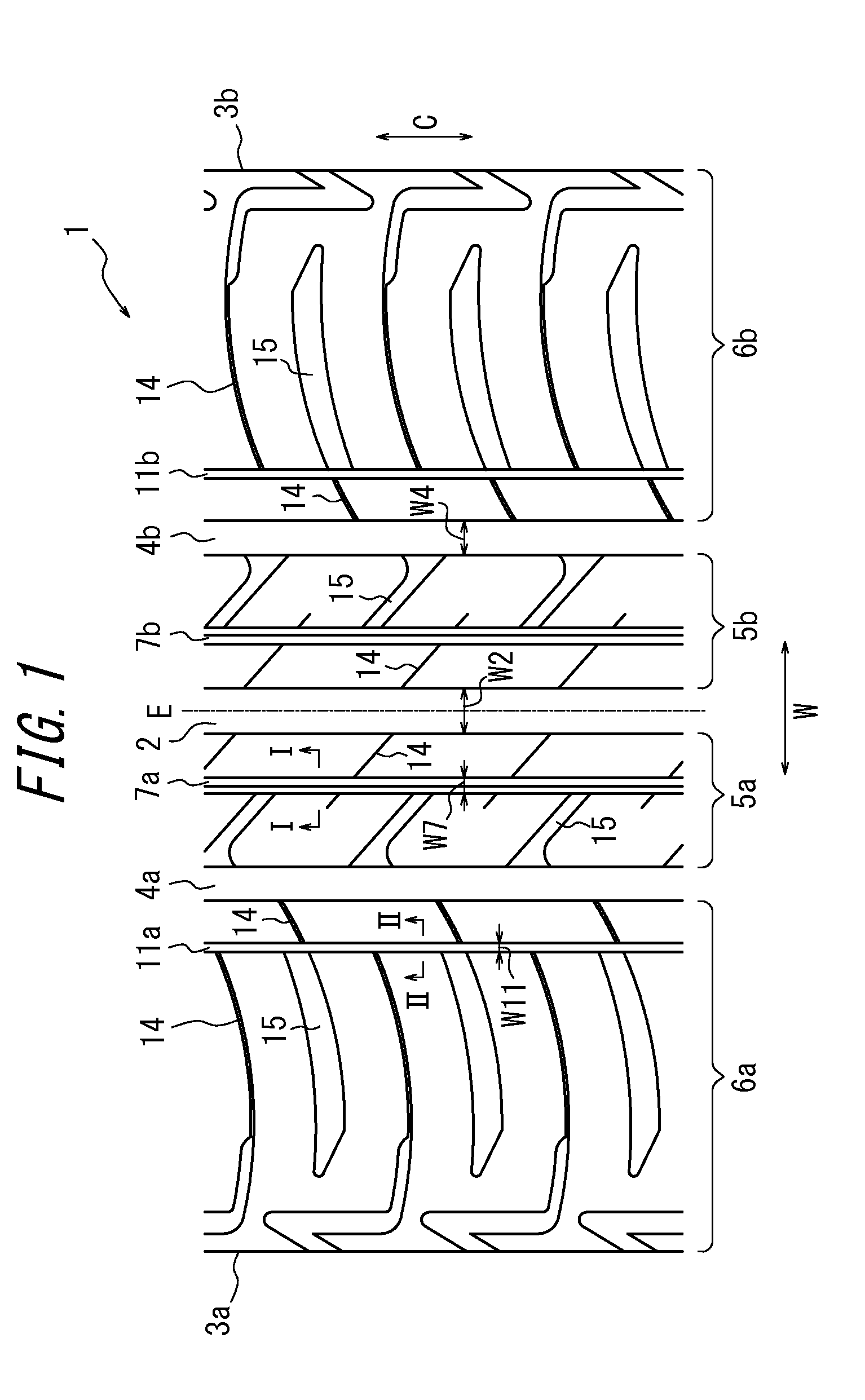
[0039]A tire having the tread pattern illustrated in FIG. 1 and a tire size of 185 / 55R16 was produced with the specifications listed in Table 1 as an Example. Note that a tire according to the present invention has structural features in the tread pattern, whereas the remaining tire structure is similar to a conventional pneumatic tire. For the sake of comparison, a tire having a similar tread pattern as the Example except for not having the cutout portion 12 in the first groove wall of the first circumferential narrow grooves was produced as Comparative Example 1, and a tire having a tread pattern with the first circumferential narrow grooves provided in the outer land portions 6a and 6b instead of the second circumferential narrow grooves was produced as Comparative Example 2. These tires were then assessed.

TABLE 1ComparativeComparativeExampleExample...


PUM


Abstract

On the surface of a tread portion (1), one central main groove (2) extends in a tire circumferential direction (C) at a pattern center, and a pair of outer main grooves (4a, 4b) extend in the tire circumferential direction (C) each at a position between the central main groove (2) and a respective one of two tread ends (3a, 3b). The central main groove (2) and the outer main grooves (4a, 4b) define central land portions (5a, 5b), and the outer main grooves (4a, 4b) and the tread ends (3a, 3b) define outer land portions (6a, 6b). Among the central land portions (5a, 5b) and the outer land portions (6a, 6b), first circumferential narrow grooves (7a, 7b) are provided only in the central land portions (5a, 5b), extend in the tire circumferential direction (C), have a narrower opening width and a shallower depth than those of the central main groove (2), and have a first groove wall (8) on the side of the outer main groove (4a, 4b) and a second groove wall (9) on the side of the central main groove (2) such that an intersection angle (θ1) between a tread surface (10) and the first groove wall (8) is larger than an intersection angle (θ2) between the tread surface (10) and the second groove wall (9).

Description

TECHNICAL FIELD[0001]The present invention relates to a pneumatic tire that has excellent on-snow performance while maintaining good steering stability on a dry road surface.BACKGROUND ART[0002]Pneumatic tires of course require sufficient steering stability on a dry road surface. Depending on the season and changes in the weather, however, such tires may also be driven on a snowy road surface and thus require on-snow performance as well.[0003]One effective method for improving steering stability on a dry road surface is, for example, to increase the tire ground contact area of the tread surface that contacts the road surface, thereby increasing the rigidity of the land portions in the entire tread.[0004]On the other hand, one effective method for improving on-snow performance is to set a high negative ratio by, for example, increasing the number of tread grooves formed on the tread surface or increasing the groove width of the tread grooves, thereby making it easier for snow to ente...

Claims


Application Information

Patent Timeline
Patent Type & Authority Applications(United States)
IPC IPC(8): B60C11/13
CPCB60C11/0306B60C11/1392B60C2011/1209B60C2011/0348B60C11/12B60C11/1323B60C2011/0372B60C2011/0395B60C11/1307B60C11/0309B60C2011/0353B60C2011/0344B60C11/1315
Inventor NAKATA, YOSHIKI
Owner BRIDGESTONE CORP
Why Eureka
Try Eureka