Connector assembly

a technology of connecting parts and connectors, applied in the direction of coupling device connection, coupling parts engagement/disengagement, electrical apparatus, etc., can solve the problems of unintentional removal and inhibiting the placement of secondary locking members in a half-fitting position

Inactive Publication Date: 2013-09-26
APTIV TECH LTD
View PDF8 Cites 12 Cited by
  • Summary
  • Abstract
  • Description
  • Claims
  • Application Information

AI Technical Summary

Benefits of technology

[0011]In a preferred embodiment, the safety spring bar provides a go / no go mechanism for the secondary locking member. A go / no go mechanism in the sense of the present invention preferably is a mechanism which provides the following: When the secondary locking member is moved in insertion direction, it is urged by the counteracting spring force of the safety spring bar essentially in a direction opposing its insertion direction. After the secondary locking member is moved, e.g. by manually pressing, beyond a releasing point, the secondary locking member is no longer urged towards its first position but preferably towards its second position. This go / no go mechanism provides the advantage that the secondary locking member can neither be placed unintentionally in an intermediate half-fitting position between its first and second position, in which it might not function properly, nor unintentionally in its second position. The inventive construction allows that, when the safety spring bar is placed in its safety position, no spring component is under tension; whereby it is assured that no spring component becomes non-serviceable due to fatigue damage.

Problems solved by technology

However, in the case described in the WO'623, it is possible to place the secondary locking member in a half-fitting position, in which it may not function properly and in which it is not fixed to the connector, and therefore can be removed unintentionally.
As long as the secondary locking member is not placed in this locking position, the spring arms are biased against the edges of the inclined channel, and due to the resulting restoring spring force they inhibit the secondary locking member to be placed in a half-fitting position unintentionally: i.e. the spring force causes the secondary locking member to move back into its pre-locked position.

Method used


Image

  • Connector assembly
  • Connector assembly
  • Connector assembly

Examples


Embodiment Construction

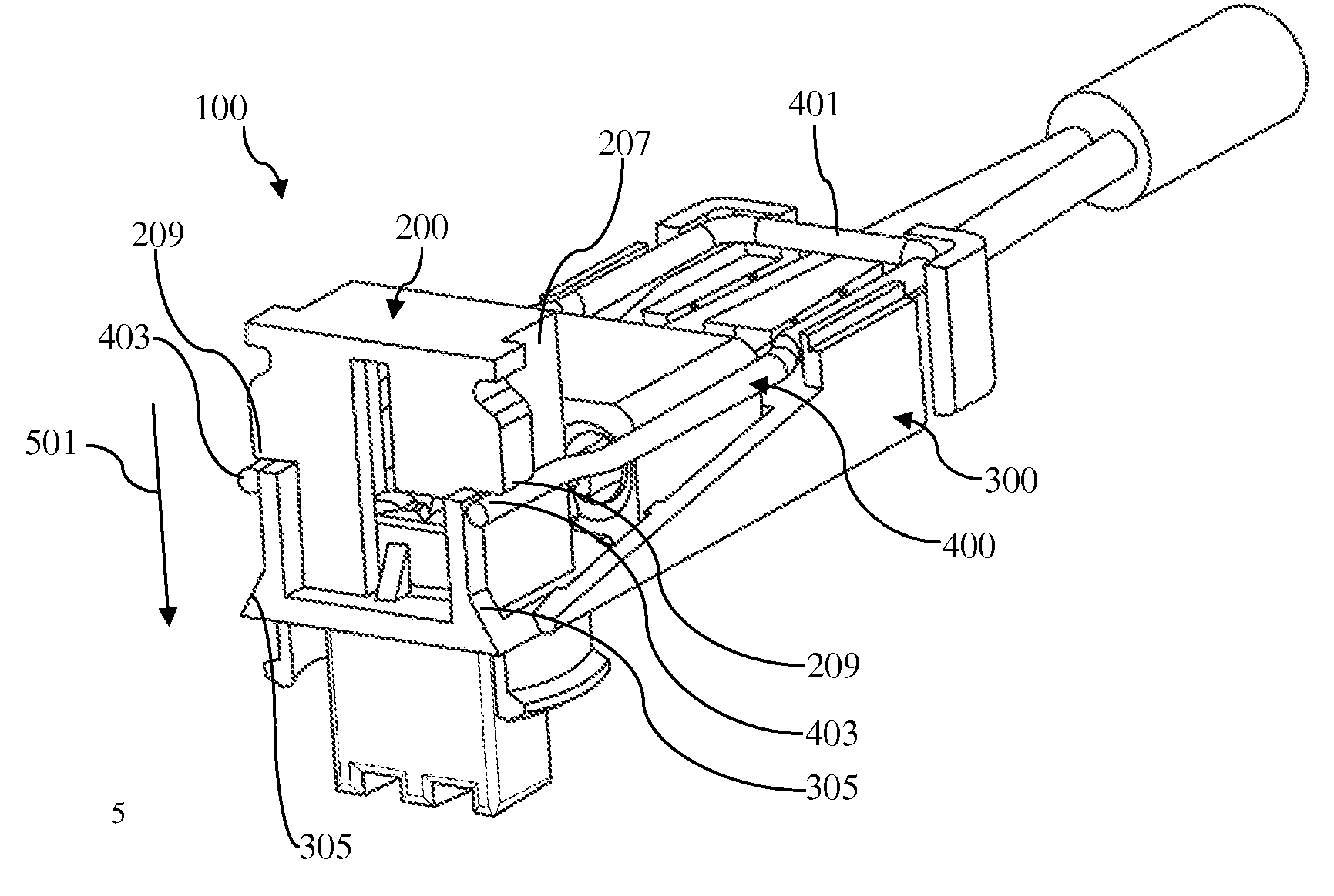
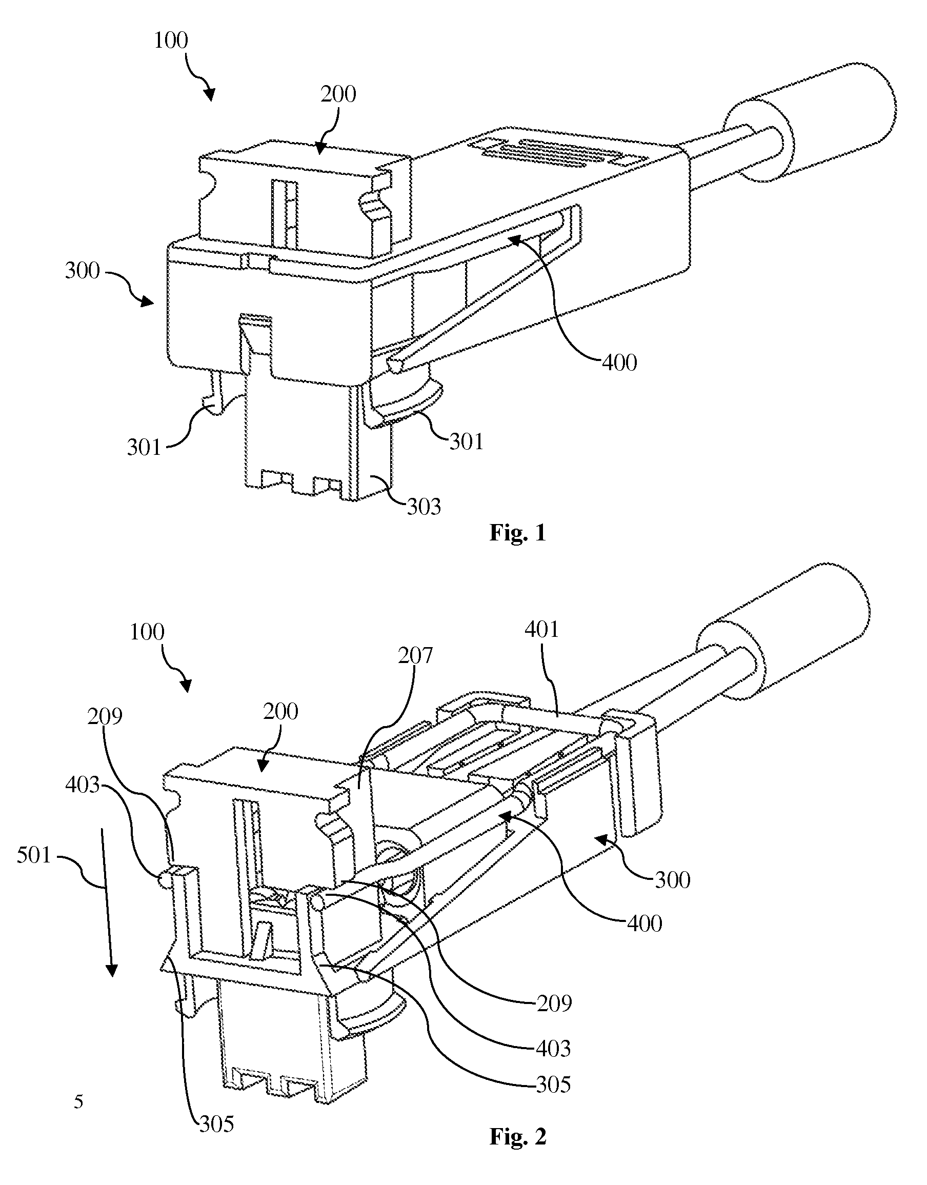
[0019]FIG. 1 shows a preferred embodiment of a connector assembly 100 according to the invention with a secondary locking member 200 mounted to a connector housing 300, and a safety spring bar 400 mounted inside the connector housing 300. In FIG. 1, the secondary locking member 200 is shown in its first position. The connector housing 300 comprises two latching arms 301 to fix the connector assembly 100 inside of a corresponding counter connector (not shown) and a connection portion 303 for establishing an electrical connection with the counter connector.

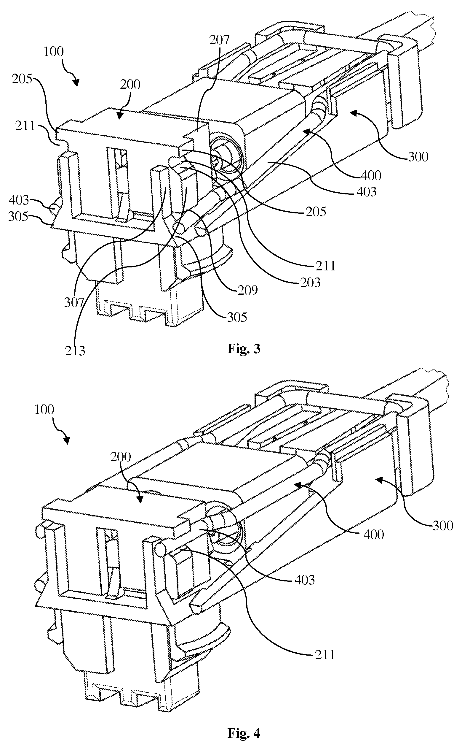
[0020]FIG. 2 shows the connector assembly 100 of FIG. 1, whereby parts of the connector housing 300 are cut such that interior components of the connector assembly 100 are visible. As one can see in this figure, in this embodiment of the invention, the safety spring bar 400 is an essentially U-shaped wire which extends within a plane essentially perpendicular to the insertion direction of the secondary locking member 200. A base 401...


PUM


Abstract

A connector assembly comprising a connector housing, a secondary locking member and a safety spring bar, whereby the secondary locking member and the safety spring bar are assigned to the connector housing. The secondary locking member is movable between a first and a second position, whereby the safety spring bar is adapted to lock the secondary locking member in its second position. The secondary locking member comprises a deflection surface adapted to engage the safety spring bar when the secondary locking member is moved in an insertion direction. Thereby, upon movement of the secondary locking member, the safety spring bar is deflected essentially in the insertion direction, urging the secondary locking member towards its first position. When the secondary locking member is placed in the second position, the safety spring bar is adapted to snap into a safety position, to lock the secondary locking member in its second position

Description

CROSS-REFERENCE TO RELATED APPLICATION[0001]This application is a national stage application under 35 U.S.C. §371 of PCT Application Number PCT / EP2011 / 068100 having an international filing date of Oct. 17, 2011, which designated the United States, which PCT application claimed the benefit of PCT Application Number PCT / IB2010 / 003233, filed Oct. 29, 2010, the entire disclosure of each of which are hereby incorporated herein by reference.TECHNICAL FIELD OF THE INVENTION[0002]The present invention relates to a connector assembly comprising a secondary locking member and a safety spring bar which preferably provides a go / no go function for the secondary locking member.BACKGROUND OF THE INVENTION[0003]In many applications, the save coupling of connectors is of high importance. For example, in the case of car safety systems, as e.g. airbag systems in passenger cars, the connectors used for the connection of an airbag to its ignition base have to be provided with reliable safety systems. To...

Claims


Application Information

Patent Timeline
Patent Type & Authority Applications(United States)
IPC IPC(8): H01R4/48
CPCH01R13/6273H01R13/6277H01R4/48H01R13/641H01R2201/26H01R13/639H01R13/627
Inventor GUNREBEN, MICHAELODORFER, FRANK
Owner APTIV TECH LTD
Why Eureka
Try Eureka