Image forming apparatus and image forming method

a technology of image forming apparatus and forming method, which is applied in the direction of digitally marking record carriers, visual presentation using printers, instruments, etc., can solve the problems of gloss unevenness, inability to solve gloss differences, and inability to achieve uniform gloss, no gloss unevenness, and no clear toner consumption. large

Active Publication Date: 2013-10-03
KONICA MINOLTA BUSINESS TECH INC
View PDF2 Cites 18 Cited by
  • Summary
  • Abstract
  • Description
  • Claims
  • Application Information

AI Technical Summary

Benefits of technology

[0015]Objects of the present invention include providing an image having uniform glossiness regardless of input image data with an image forming apparatus, and providing an image having stable glossiness with no gloss unevenness without consuming a large amount of a clear toner with an image forming apparatus.

Problems solved by technology

Hence, if a clear toner is made to adhere onto such a sheet uniformly, gloss unevenness is generated.
However, the toner adhesion amount of a color image depends on a gradation-toner adhesion amount characteristic of each of Y, M, C and K. Hence, the total toner adhesion amount of the color toners and the clear toner on a sheet corrected by the clear toner on the basis of the inversion signal of the input image signal is not uniform, so that the technology disclosed in Patent Document 1 cannot solve the gloss difference (gloss unevenness).
In addition, even when the total toner adhesion amount corrected by the clear toner is uniform, if the total height of the color toner images and the clear toner image is not uniform, roughness is produced on the image surface, and accordingly the gloss difference is generated.
Further, although the technology disclosed in Patent Document 2 can reduce the gloss difference between an image portion and a non-image portion, the technology cannot reduce the gloss unevenness in the image portion because the clear toner is developed uniformly on an image.
Further, although the technology disclosed in Patent Document 3 can make the glossiness uniform in an image portion of each of Y, M, C and K regardless of gradations, the technology generates the gloss / density unevenness among Y, M, C and K. In addition, as the number of colors (Y, M, C and K) laid on top of each other increases, namely, from a primary color to a secondary color, a tertiary color and then a quartic color, the gloss difference increases, and accordingly the roughness on the surface of the recording sheet becomes noticeable.
Accordingly, images cannot be stably outputted.
As a result, the technology disclosed in Patent Document 3 has a problem that if a clear toner image is formed on color toner images, a large amount of a clear toner is consumed, or desired gloss cannot be made because of the color shift.

Method used


Image

  • Image forming apparatus and image  forming method
  • Image forming apparatus and image  forming method
  • Image forming apparatus and image  forming method

Examples


first embodiment

[0053]In the following, an image forming apparatus in accordance with a first embodiment of the present invention is described with reference to the drawings.

[Configuration of Image Forming Apparatus 1]

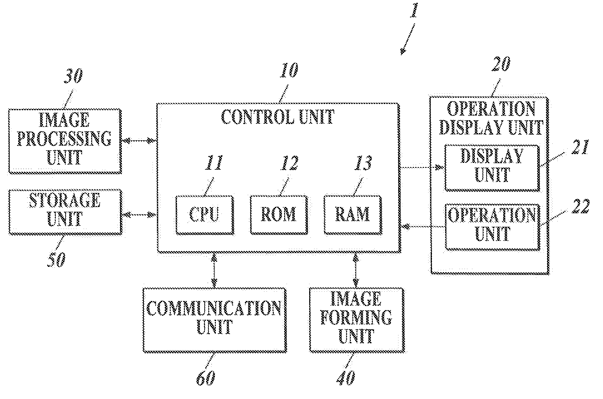
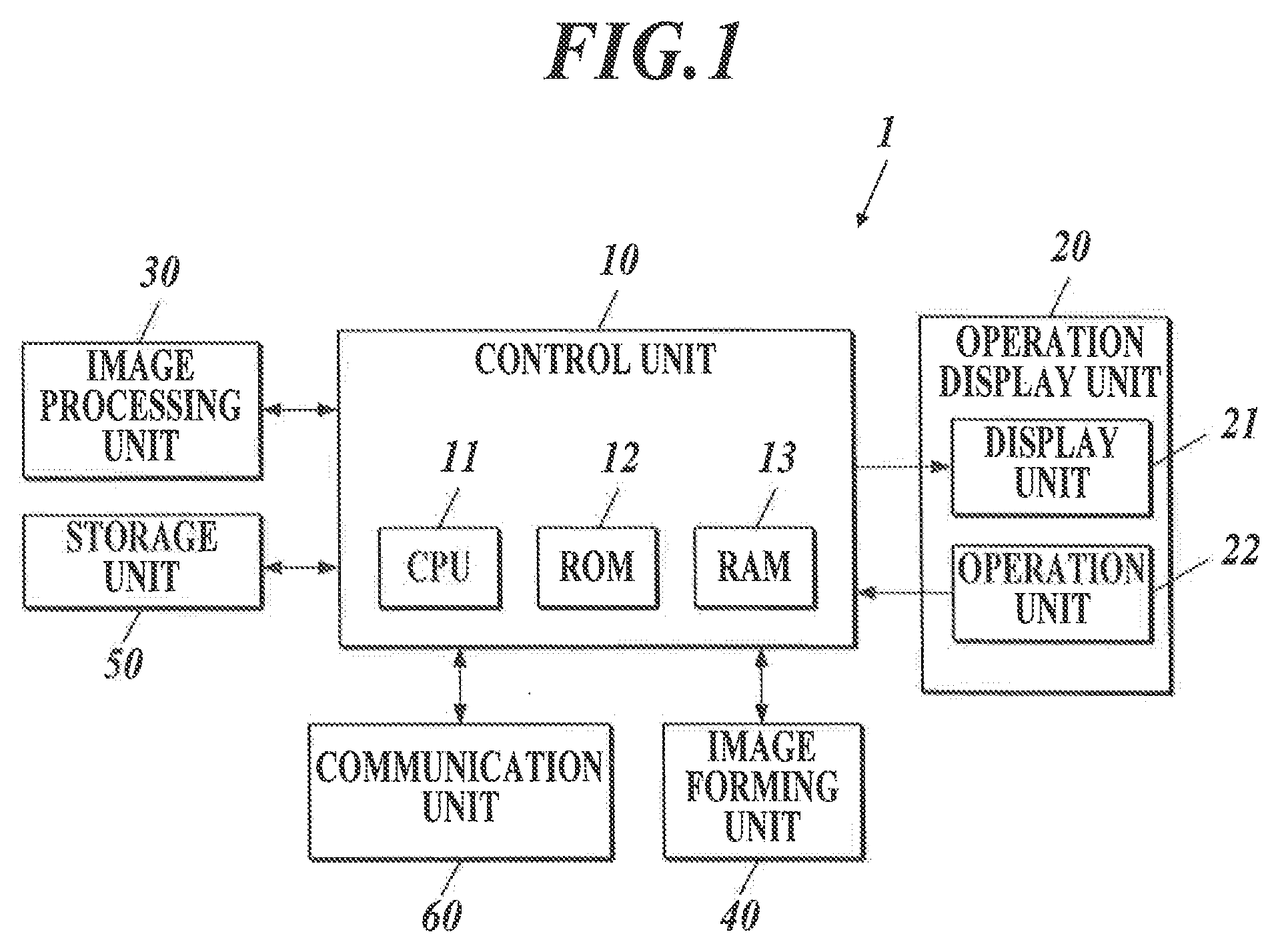
[0054]FIG. 1 is a block diagram showing a functional configuration of an image forming apparatus 1. The image forming apparatus 1 is a color image forming apparatus using electrophotographic process technology.

[0055]As shown in FIG. 1, the image forming apparatus 1 includes a control unit 10, an operation display unit 20, an image processing unit 30, an image forming unit 40, a storage unit 50 and a communication unit 60. These units are connected to each other via a not-shown bus.

[0056]The control unit 10 includes a CPU (Central Processing Unit) 11, a ROM (Read Only Memory) 12 and a RAM (Random Access Memory) 13. The CPU 11 of the control unit 10 reads a system program and various processing programs stored in the ROM 12 so as to load the read programs to the RAM 13, and performs cen...

second embodiment

[0108]In the following, a configuration and operation of an image forming apparatus in accordance with a second embodiment of the present invention are described with reference to the drawings in detail. In the embodiment, as the image forming apparatus, a color image forming apparatus 1 is described. However, this is not a limitation, and hence the present invention can be realized, for example, by a monochrome image forming apparatus too.

[Configuration of Image Forming Apparatus 1]

[0109]A functional configuration of the image forming apparatus 1 of the second embodiment is almost the same as that shown in FIG. 1. Hence, different points are described in the following.

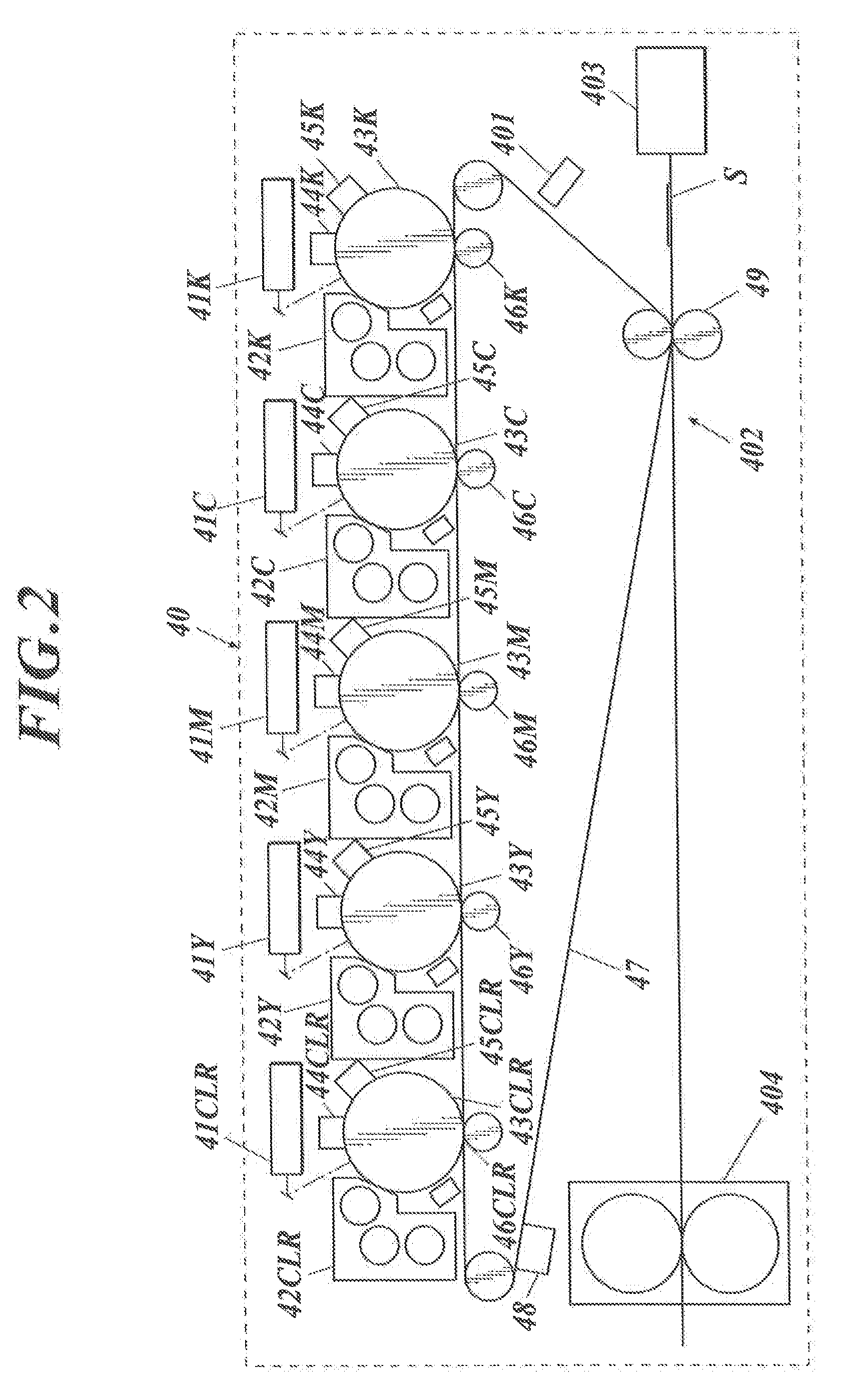
[0110]FIG. 12 schematically shows a configuration of the image forming unit 40 of the image forming apparatus 1 in accordance with the second embodiment. In the first embodiment, as shown in FIG. 2, the image forming units, which respectively use yellow, magenta, cyan, black and clear toners, are disposed in a horizon...


PUM


Abstract

An image forming apparatus includes an image forming unit, a storage unit, an image processing unit and a control unit. The image processing unit (i) calculates a summed height of a color toner image formed on a sheet by summing up a height of the color toner image on the basis of input image data, (ii) calculates, on the basis of a target value for glossiness stored in the storage unit, a target total height of the color toner image and a clear toner image to realize the target value for glossiness, and (iii) calculates a height of the clear toner image by subtracting the summed height from the target total height. On the basis of the calculated height of the clear toner image, the control unit adjusts the height of the clear toner image formed on the sheet.

Description

BACKGROUND OF THE INVENTION[0001]1. Field of the Invention[0002]The present invention relates to an image forming apparatus and an image forming method.[0003]2. Description of the Related Art[0004]In general, an electrographic image forming apparatus irradiates (exposes) charged photosensitive drums with laser light based on image data so as to form electrostatic latent images thereon, and makes toners made of colored powders adhere to the electrostatic latent images so as to visualize the electrostatic latent images and accordingly form toner images on sheets of paper.[0005]In an electrographic image forming apparatus, glossiness of images formed on sheets changes as a gradation level changes. This is because, in the electrographic system, gradations of color toner images, such as Y (yellow) toner images, M (magenta) toner images, C (cyan) toner images and K (black) toner images, are expressed by area coverage modulation (screens or halftone dots), and accordingly roughness exists ...

Claims


Application Information

Patent Timeline
Patent Type & Authority Applications(United States)
IPC IPC(8): G06K15/14
CPCG06K15/14G03G2215/0081G03G15/6585H04N1/54
Inventor SAITO, KAZUHIROTANAKA, HIDEAKIHIRATA, KATSUYUKIHARASHIMA, TAKASHI
Owner KONICA MINOLTA BUSINESS TECH INC
Why Eureka
Try Eureka