Color measuring device, image forming apparatus, colorimetric system and color measuring method

a color measurement and image technology, applied in the field of color measurement devices, image forming apparatus, color measurement systems, etc., can solve the problems of difficult to obtain stable image data from the subject of the colorimetric target, difficult to maintain a positional relation between the subject, the light source and the color video camera, and the cost of the spectrophotometer

Active Publication Date: 2013-10-03
RICOH KK
View PDF10 Cites 59 Cited by
  • Summary
  • Abstract
  • Description
  • Claims
  • Application Information

AI Technical Summary

Problems solved by technology

However, since the spectrophotometer is expensive, it is desirable to perform high-accuracy colorimetry using a cheaper device.
However, in the technique discussed in Japanese Patent No. 3129502, it is difficult to maintain a positional relation among the subject, a light source, and the color video camera, and an imaging condition changes each time image capturing is performed.
Thus, it is likely that it is difficult to obtain stable image data from the subject of the colorimetric target.

Method used


Image

  • Color measuring device, image forming apparatus, colorimetric system and color measuring method
  • Color measuring device, image forming apparatus, colorimetric system and color measuring method
  • Color measuring device, image forming apparatus, colorimetric system and color measuring method

Examples


first modification

[0218

[0219]FIG. 28 is a vertical cross-sectional view of an image capturing unit 42A of the first modification and a cross-sectional diagram at the same position as the vertical cross-sectional view of the image capturing unit 42 illustrated in FIG. 5A.

[0220]In the image capturing unit 42A of the first modification, an opening portion 427 separate from the opening portion 425 through the colorimetric target patch CP is captured is formed in the bottom portion 421a of the housing 421. Further, the chart board 410 is arranged to block the opening portion 427 from the external side of the housing 421. In other words, in the image capturing unit 42, the chart board 410 is arranged on the internal side of the housing 421 facing the sensor unit 430 of the bottom portion 421a, whereas in the image capturing unit 42A of the first modification, the chart board 410 is arranged on the external side of the bottom portion 421a of the housing 421 facing the recording medium P.

[0221]Specifically, ...

second modification

[0223

[0224]FIG. 29 is a vertical cross-sectional view of an image capturing unit 42B of the second modification and a cross-sectional diagram at the same position as the vertical cross-sectional view of the image capturing unit 42 illustrated in FIG. 5A.

[0225]In the image capturing unit 42B of the second modification, similarly to the image capturing unit 42A of the first modification, the chart board 410 is arranged on the external side of the bottom portion 421a of the housing 421. In the image capturing unit 42A of the first modification, the chart board 410 adheres to the bottom portion 421a of the housing 421 through an adhesive or the like and is integrated with the housing 421, whereas in the image capturing unit 42B of the second modification, the chart board 410 is removably held to the housing 421.

[0226]Specifically, for example, similarly to the image capturing unit 42A of the first modification, a concave portion communicating with the opening portion 427 is formed on th...

third modification

[0228

[0229]FIG. 30 is a vertical cross-sectional view of an image capturing unit 42C of the third modification and a cross-sectional diagram at the same position as the vertical cross-sectional view of the image capturing unit 42 illustrated in FIG. 5A.

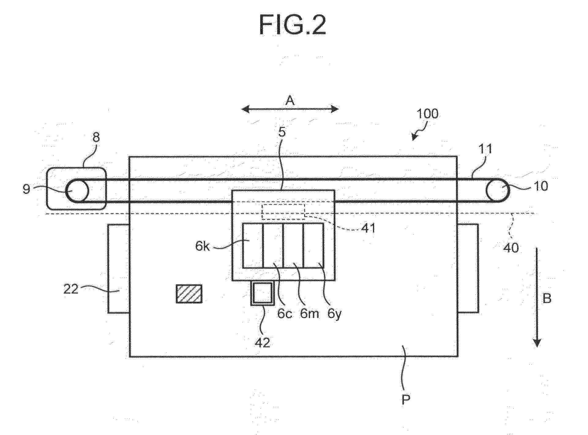
[0230]In the image capturing unit 42C of the third modification, a mist blocking permeation member 450 that blocks the opening portion 425 of the housing 421 is added. The image forming apparatus 100 according to the present embodiment is configured to eject ink from a row of nozzles of the print head 6 mounted in the carriage 5 onto the recording medium P on the platen plate 22 and form an image on the recording medium P as described above. For this reason, when ink is ejected from a row of nozzles of the print head 6, mist-like small ink particles (hereinafter a small ink particle is referred to as a “mist”) are generated. Further, when mists generated at the time of image forming enter the inside of the housing 421 from the outside...


PUM


Abstract

A color measuring device includes a housing; a sensor unit configured to capture an image of a region, the sensor unit being held to the housing; an illumination light source configured to illuminate the region, the illumination light source being held to the housing; a detecting unit configured to detect a distance between predetermined two points from image data of the region obtained by the sensor unit; a correcting unit configured to correct the image data including a subject whose color is to be measured according to a ratio of the detected distance to a reference distance; and a calculating unit configured to calculate a colorimetric value of the subject based on the corrected image data.

Description

CROSS-REFERENCE TO RELATED APPLICATIONS[0001]The present application claims priority to and incorporates by reference the entire contents of Japanese Patent Application No. 2012-075022 filed in Japan on Mar. 28, 2012 and Japanese Patent Application No. 2013-032538 filed in Japan on Feb. 21, 2013.BACKGROUND OF THE INVENTION[0002]1. Field of the Invention[0003]The present invention relates to a color measuring device, an image forming apparatus, a colorimetric system, and a color measuring method.[0004]2. Description of the Related Art[0005]In an image forming apparatus such as printers, processing called color management is performed in order to suppress fluctuation of an output by a characteristic specific to a device and increase reproducibility of an output to an input. For example, the color management is performed by the following technique. First of all, an image of a color chart (patch) of a reference color is actually output by an image forming apparatus, and a color measurin...

Claims


Application Information

Patent Timeline
Patent Type & Authority Applications(United States)
IPC IPC(8): H04N1/00H04N1/60
CPCH04N1/00082G01J3/462H04N1/6044H04N1/60
Inventor SHIGEMOTO, MASAHIROSATOH, NOBUYUKITAKEI, KAZUSHISUZUKI, HIDEAKIIWANAMI, SATOSHI
Owner RICOH KK
Why Eureka
Try Eureka